Mount installation on horizontal bracket – CHIEF KWT110 User Manual
Page 17
Installation Instructions
KWT-110
17
10. Repeat steps 6 through 9 for each mounting hole.
Figure 32
11. Place wall track accessory (A) over anchors and align
mounting holes in display mount with holes in anchors. (See
Figure 33)
12. Insert 1/4-20 x 1 3/4" Phillips pan head screws (D) through
corresponding mounting hole on wall track accessory and
into anchor (C) and tighten until flush against mount. DO
NOT overtighten! (See Figure 33)
13. Repeat steps 11 through 12 for remaining mounting holes.
WARNING:
IMPROPER INSTALLATION CAN LEAD TO
EQUIPMENT FALLING CAUSING SERIOUS PERSONAL
INJURY OR DAMAGE TO EQUIPMENT! Overtightening of
mounting hardware can damage the steel studs. DO NOT
overtighten mounting hardware!
Figure 33
Mount Installation on Horizontal Bracket
WARNING:
Exceeding the weight capacity can result in
serious personal injury or damage to equipment! It is the
installer’s responsibility to make sure the weight of each
component attached to the KSA-1022 wall track accessory
does not exceed 25 lbs (11.3 kg) or the specific weight limit
for the attached mounting device.
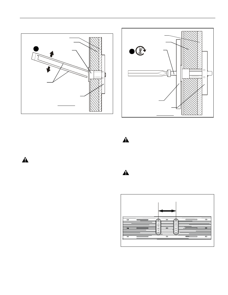
WARNING:
For horizontal mounting on wood or steel
studs, a minimum distance of 8" must exist between mounted
devices. (See Figure 34)
Figure 34
1.
Remove side cover to slide locking plate brackets (J) into
wall track accessory (A) at the desired mounting location.
(See Figure 35)
NOTE:
Locking plate brackets must be inserted into the top
channel and second channel from the bottom.
Plastic Straps
Drywall
Anchor Metal Channel
Plastic Cap
SIDE VIEW
9
Steel Stud
Drywall
Anchor Metal Channel
SIDE VIEW
(D) x 4 or 6
9
Steel Stud
(A)
8" minimum