Keyboard and wrist pad installation – CHIEF KWT110 User Manual
Page 20
KWT-110
Installation Instructions
20
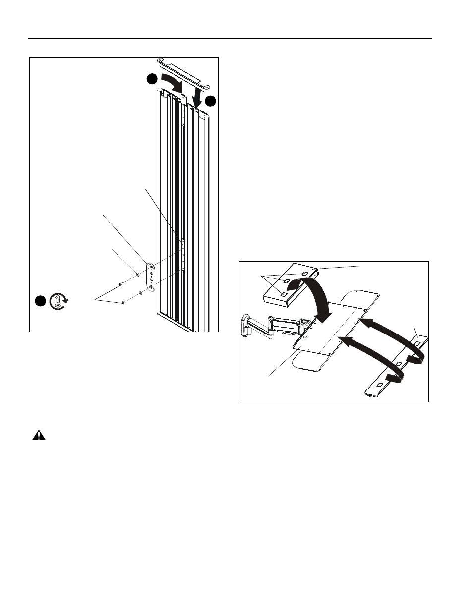
Figure 40
3.
Use 1/8" hex key (BB) to install #10 button head cap screws
(V) through #10 washers (N) and wall plate (H) into center
holes of locking plate brackets (J). (See Figure 40)
NOTE:
Wall brackets must be secured by installing screws
through the top and bottom holes of the wall plate (H).
(See Figure 40)
4.
Ensure wall plate (H) is vertical, then tighten screws (V).
CAUTION:
Overtightening screws may cause wall bracket
to compress into wall track accessory surface, resulting in
difficult mount installation or improper engaging of set screw
in later step.
5.
Insert top of Centris display mount (B) over lip on top of wall
plate (H) on preferred location. (See Figure 36)
6.
Swing Centris display mount (B) down flush against wall
track accessory (A). (See Figure 36)
7.
Use 5/32" hex driver (AA) to tighten set screw in bottom of
wall mount. (See Figure 37)
NOTE:
Ensure set screw engages on back side of wall plate to
properly secure wall mount.
8.
Insert top of keyboard tray mount (C) over lip on top of the
other wall plate (H). (See Figure 38)
9.
Swing keyboard tray mount (C) down flush against wall.
(See Figure 38)
10. Use 5/32" hex driver (AA) to tighten set screw in bottom of
wall mount. (See Figure 37)
NOTE:
Ensure set screw engages on back side of wall plate to
properly secure wall mount.
Keyboard and Wrist Pad Installation
1.
Remove adhesive backing from one side of hook and loop
connectors (M).
2.
Place hook and loop connectors (M) on bottom of the
keyboard and bottom of wrist pad (F) approximately as
shown. (See Figure 41)
NOTE:
Place connectors only on flat sections of the keyboard
to ensure that they stick to the surface.
3.
Remove the adhesive backing from the other side of the
hook and loop connectors (M).
4.
Firmly place keyboard on keyboard tray making sure to
leave room for the wrist pad if necessary. (See Figure 41)
5.
Firmly place wrist pad (F) on keyboard tray in front of the
keyboard. (See Figure 41)
Figure 41
((B)
(V) x 2
3
(N) x 2
(H)
1
2
(J)
keyboard
(F)
(C)
(M) x 6