Mount installation on vertical bracket – CHIEF KWT110 User Manual
Page 19
Installation Instructions
KWT-110
19
7.
Use 5/32" hex driver (AA) to tighten set screw in bottom of
wall mount. (See Figure 37)
NOTE:
Ensure set screw engages on back side of wall plate to
properly secure wall mount.
Figure 37
8.
Insert top of keyboard tray mount (C) over lip on top of the
other wall plate (H). (See Figure 38)
9.
Swing keyboard tray mount (C) down flush against wall.
(See Figure 38)
Figure 38
10. Use 5/32" hex driver (AA) to tighten set screw in bottom of
wall mount. (See Figure 37)
NOTE:
Ensure set screw engages on back side of wall plate to
properly secure wall mount.
Mount Installation on Vertical Bracket
WARNING:
Exceeding the weight capacity can result in
serious personal injury or damage to equipment! It is the
installer’s responsibility to make sure the weight of each
component attached to the KSA-1022 wall track accessory
does not exceed 25 lbs (11.3 kg) or the specific weight limit
for the attached mounting device.
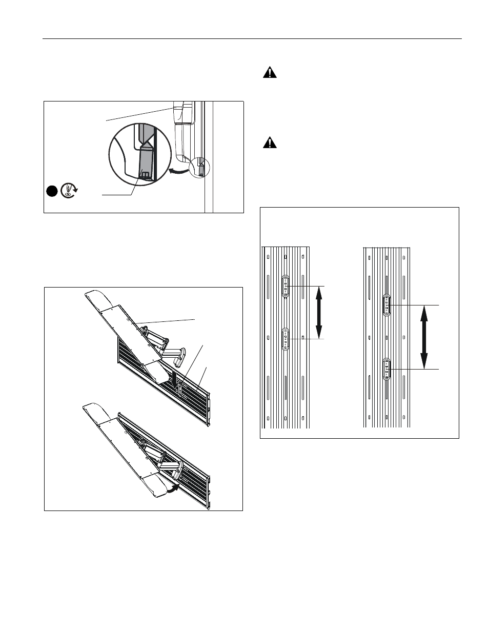
WARNING:
For vertical mounting on wood or steel studs, a
minimum distance of 8" must exist between mounted
devices. For vertical mounting on drywall, a minimum
distance of 16" must exist between mounted devices. (See
Figure 39)
Figure 39
1.
Remove side cover to slide locking plate brackets (J) into
wall track accessory (A) at the desired mounting location.
(See Figure 40)
NOTE:
Locking plate brackets must be inserted into center
channel on wall track accessory.
2.
Reinstall side cover to wall track accessory after all locking
plate brackets have been inserted. (See Figure 40)
(B or C)
Set
Screw
7
(C)
(H)
(A)
Wood or Steel Studs
Drywall
8"
minimum
16"
min