Asus M2NPV-VM User Manual
Page 42
1 - 3 2
1 - 3 2
1 - 3 2
1 - 3 2
1 - 3 2
C h a p t e r 1 : P r o d u c t i n t r o d u c t i o n
C h a p t e r 1 : P r o d u c t i n t r o d u c t i o n
C h a p t e r 1 : P r o d u c t i n t r o d u c t i o n
C h a p t e r 1 : P r o d u c t i n t r o d u c t i o n
C h a p t e r 1 : P r o d u c t i n t r o d u c t i o n
1 3 .
1 3 .
1 3 .
1 3 .
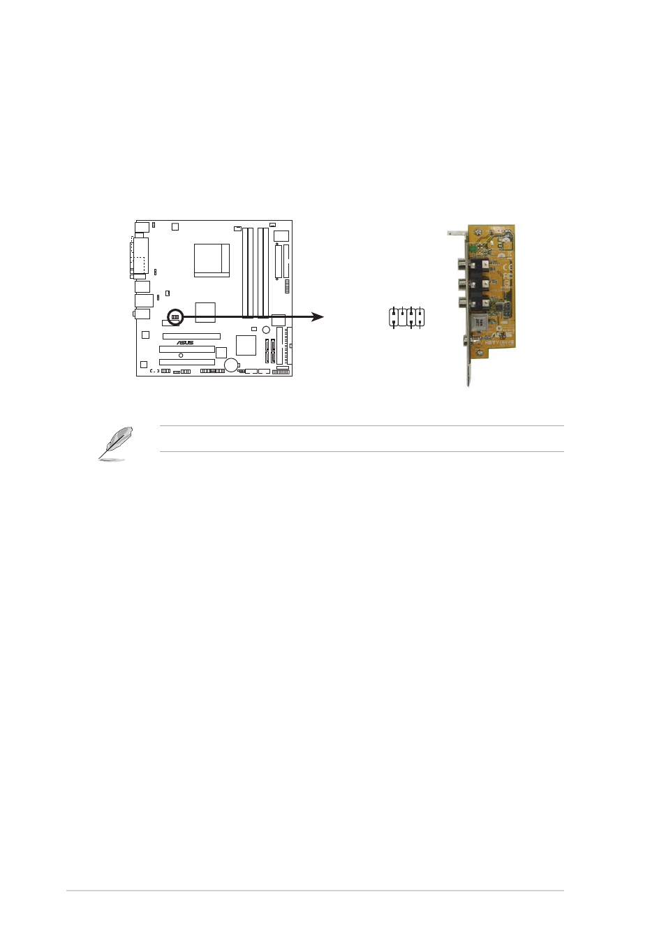
1 3 . T V - o u t c o n n e c t o r ( 8 - 1 p i n T V _ O U T )
T V - o u t c o n n e c t o r ( 8 - 1 p i n T V _ O U T )
T V - o u t c o n n e c t o r ( 8 - 1 p i n T V _ O U T )
T V - o u t c o n n e c t o r ( 8 - 1 p i n T V _ O U T )
T V - o u t c o n n e c t o r ( 8 - 1 p i n T V _ O U T )
This 8-1 pin connector is for the TV-out port module that allows you
to connect a television to your system. Connect one end of the
HDTV-out cable to this connector and the other end to the TV-out
module.
M2NPV-VM
®
M2NPV-VM TV out connector
TV_OUT
GND
Pb
PR
GND
Y
+5V
+12V
•
RGB and TV-out can not be used simultaneously.
- Xonar DX (80 pages)
- Xonar DX (10 pages)
- PCI Express Audio Card Xonar DX (70 pages)
- Xonar D2X (84 pages)
- D2X (88 pages)
- Audio Card Xonar D2X (70 pages)
- Xonar D2X (88 pages)
- ROG Xonar Phoebus (72 pages)
- ROG Xonar Phoebus (122 pages)
- Xonar DSX (26 pages)
- Xonar DSX (29 pages)
- Xonar DGX (33 pages)
- Xonar DGX (58 pages)
- Xonar DGX (38 pages)
- Xonar DG (28 pages)
- Xonar DG (54 pages)
- Xonar DG (58 pages)
- Xonar DG (32 pages)
- Xonar Essence ST (52 pages)
- Xonar Essence ST (35 pages)
- Xonar Essence ST (40 pages)
- Xonar Essence ST (53 pages)
- Xonar DS (54 pages)
- Xonar DS (33 pages)
- Xonar Xense (45 pages)
- Xonar Xense (47 pages)
- Xonar Xense (70 pages)
- Xonar U3 (56 pages)
- Xonar U3 (38 pages)
- Xonar Essence STX (10 pages)
- Xonar Essence STX (32 pages)
- Xonar Essence STX (49 pages)
- XONAR D1 E4009 (72 pages)
- Xonar D1 (72 pages)
- Xonar D1 (80 pages)
- Xonar D1 (10 pages)
- Xonar Essence One (7 pages)
- Xonar Essence One (5 pages)
- Xonar HDAV 1.3 (100 pages)
- Motherboard M4A78-EM (64 pages)
- A7N8X-VM/400 (64 pages)
- K8V-XE (86 pages)
- K8V-XE (20 pages)
- M2R32-MVP (60 pages)
- M2R32-MVP (160 pages)