CHIEF K-Series User Manual
Page 13
Installation Instructions
Model: K-Series
13
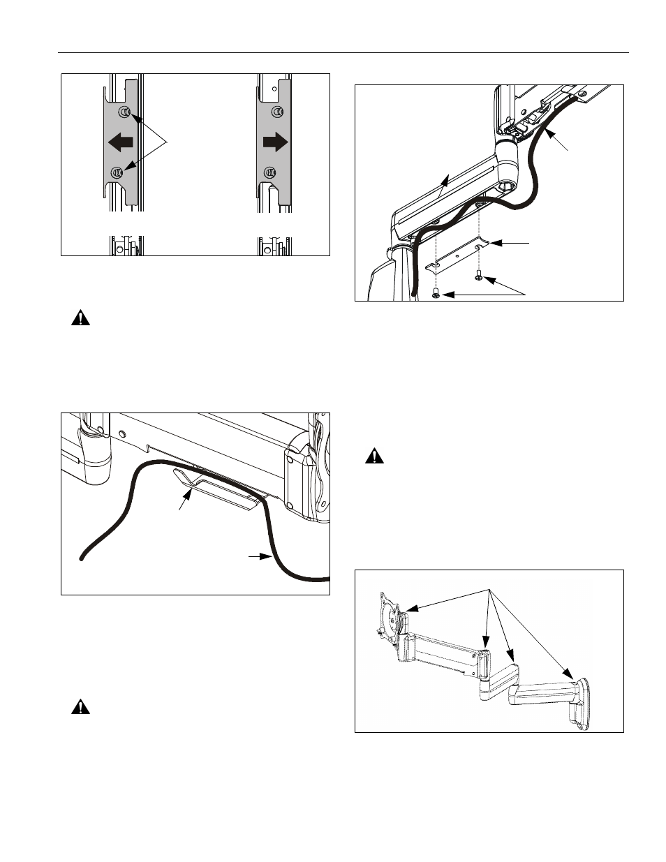
Figure 21: Height Adjustable Arm -
Cable Management Bracket
CAUTION: Ensure that adequate cable slack exists for
movement of display, and that cables will not be
pinched when bracket is closed.
3.
Carefully insert cables into bracket (See Figure 22).
Figure 22: Height Adjustable Arm - Cable Path
4.
Close cable management bracket by sliding it back
towards the centerline of the arm (See Figure 21).
NOTE: If necessary, cable management bracket attach
screws may be tightened using hex key (30).
CAUTION: Ensure that adequate cable slack exists for
movement of display, and that cables will not be
pinched by installation of cover (10) or screws (20).
5.
Carefully insert cables in cavity located in lower
portion of static mount arm (See Figure 23).
6.
Using Phillips screwdriver, install cover (10) with two
screws (20).
Figure 23: Static Arm - Cable Path
NOTE: Installation is complete.
NOTE: Cable ties (provided with certain models) may be
used for additional cable management capability.
ADJUSTMENT
ARM
PIVOT / SWING
CAUTION: If washer (80) has been used to assemble
KCY-210/-220 arms, then forced movement of arms
without loosening screw (30) will damage arm and/or Y-
connector (See Figure 18)(See Figure 20).
1.
Using 3/16" hex key, slightly loosen or tighten the
adjustment screw(s) as necessary (See Figure 24).
Figure 24: Pivot / Swing Arm Adjustment
OPEN Position
CLOSED Position
View from Bottom
Attach
Screws
Cable Path (typical)
NOTE: Display not shown for clarity.
Cable Management
Bracket (in open position)
90
20
Cable Path
(typical)
10
Adjustment Screws