CEMB USA C71 (C) User Manual
Page 7
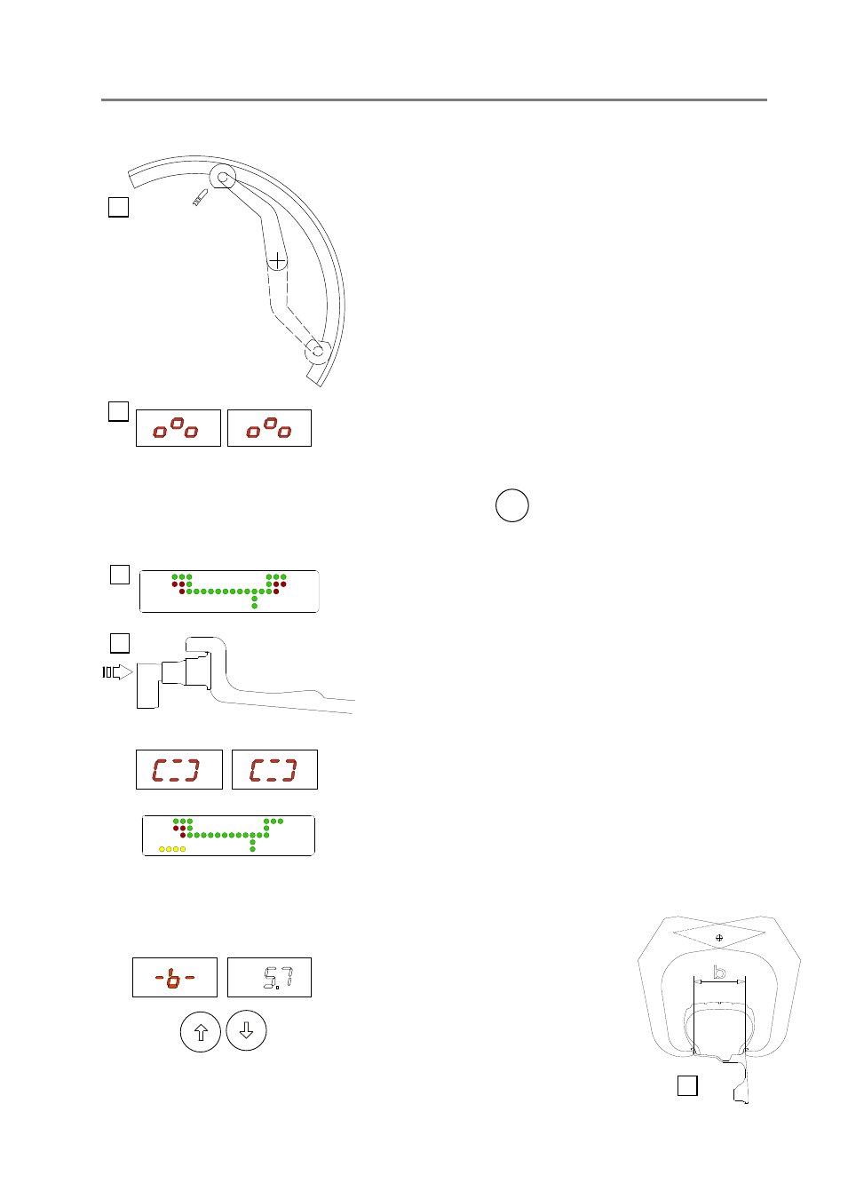
POS. A
POS. B
5
b
5c
5a
5b
5d
I 0410 -
6
I 0410 -
7
GB
GB
5 - Instructions for use of the wheel balancer
5.1 - Using the gauge installed on the machine
5.1.1 - Data setting
For clamp weights, use the gauge in the top position A.
For adhesive weights, use the gauge as preferred in top position A or
bottom position B.
Note: Always use the round part of the striker plate resting on
the rim.
Indication of gauge in movement
5.2 - Automatic presetting
The machine automatically detects the correct balancing program for steel and aluminium rims (ALU-S).
The counterweight position proposed may be changed using the two
ALU
buttons.
5.2.1 - Steel or aluminum wheel rims. Sprung counterweights
Pull out the gauge as far as the inner edge of the rim. Hold it in this
position until a “beep” is heard.
Indication of dimensions acquired
Return the gauge to rest position. The machine has automatically
detected DISTANCE + DIAMETER and goes to MANUAL WIDTH
SETTING.
- The nominal width is normally stamped
on the rim; if not, proceed to measure
dimension “b” with the calibre gauge
(supplied as standard).