CEMB USA C71 (C) User Manual
Page 4
2
2a
3
A
B
I 0410 -
4
I 0410 -
5
GB
GB
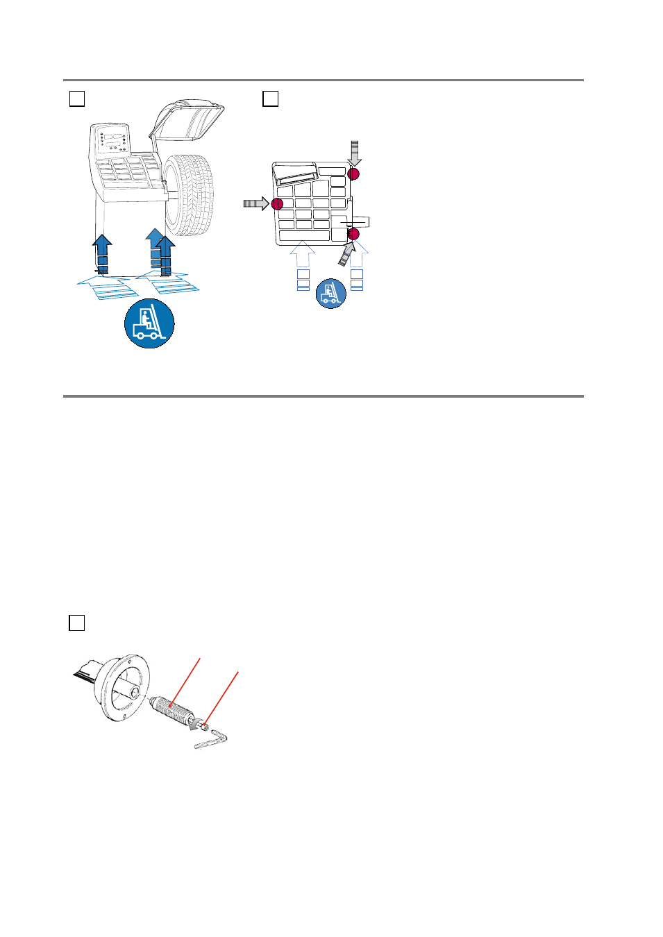
2 - Handling and lifting
3 - Startup
3.1 - Anchoring
The machine can operate on any flat non resilient floor.
Make sure that the machine rests solely on the three support points provided (Fig.2a).
3.2 - Electrical connection
The machine is supplied with a single-phase mains cable plus earth (ground).
(any extension cables must have a cross-section of no less than 2.5 mm
2
).
The power supply voltage (and mains frequency) is indicated on the machine identification plate and cannot be
changed. Connection to the mains must always be made by expert personnel.
The machine must not be set up without proper earthing.
Connection to the mains should be through a slow acting safety switch rated at 16 A (230V). See enclosed diagram.
3.3 - Flange mounting
NOTE: DO NOT LIFT THE WHEEL
BALANCER USING OTHER GRIPS
The wheel balancer is supplied complete with cone flanges
for fixing wheels with a central hole. To mount other optional flange
adaptors :
a) Remove the threaded end-piece A after unscrewing the screw B.
b) Mount the new flange (see attached sheets).
NOTE: CAREFULLY CLEAN THE COUPLING SURFACES BEFORE
PERFORMING ANY OPERATION.
3.4 - Wheel guard assembly and adjustment (optional)
a)
Fix the components to the base as described in the attachment
“WHEEL GUARD ASSEMBLY SEQUENCE” at
the end of the manual.
Note: Do not lean on the guard during the wheel balancing cycle.