CEMB USA C212 (A) User Manual
Page 8
I 0648
- 8
FI
FE
GB
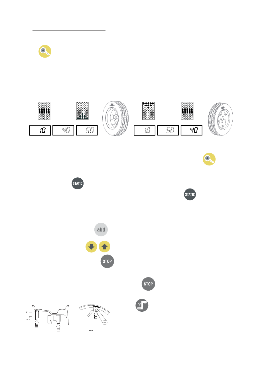
5.2 - RESULT OF MEASUREMENT
►
Unbalance display pitch:
►
Car = 1/5 g (.1/0.25 Oz) Truck = 10/50 g (.25/1 Oz)
When
is pressed, the unbalance is displayed with pitch:
Car = 1 g
Truck = 10 g
.1
Oz
.25
Oz
Unbalance display threshold
►
Car = 5 g (.4 Oz)
Truck = 50 g (2 Oz)
Inside correction
Outside correction
After performing a balancing spin, the amounts of unbalance are shown on the digital readouts.
Digital readouts with LED lit up indicate the correct angular wheel position to mount the counterweights (12 o’clock
positi
on).
If the unbalance is less than the threshold selected,
0
is displayed instead of the unbalance; with
it is possible
to read the values below the threshold chosen.
5.2.1 - STATIC UNBALANCE
►
It is selected by pressing
and is shown on the central display. The position is indicated on the displays 3 and 4.
The value can always be displayed (see
SETUP
); in this case, to see the position press
.
5.2.2 -
►
MODIFYING SET DIMENSIONS
If the wheel dimensions have been entered incorrectly, the parameters can be modifi ed without repeating the balan-
cing spin by pressing :
access parameter modifi cation
→
(select
to modify: (a) distance, (b) width, (d) diameter
→
to obtain the new measurement
or:
pull out the gauge to repeat the measurement
→
to obtain the new measurement.
5
►
.2.3 -
EXACT POSITIONING OF THE ADHESIVE WEIGHT BY MEANS OF THE GAUGE WITH CLIPS
Press
▪
Fit
▪
the correction weight in the specifi c gauge seat with the
adhesive part facing upwards
Bring the wheel into correct angular position for the plane
▪
to be corrected
Pull out the gauge: the approach of the weights to the correc-
▪
tion positions is indicated by the LEDs number 19
When the weight application distance has been reached a beep
▪
is sounded (can be deactivated).
Turn the gauge until the correction weight adheres to the rim
▪
using the weight pusher.