J&M GW15t-1 User Manual
Page 7
GC15
t
-1 G
ravity
W
aGon
a
ssembly
-7-
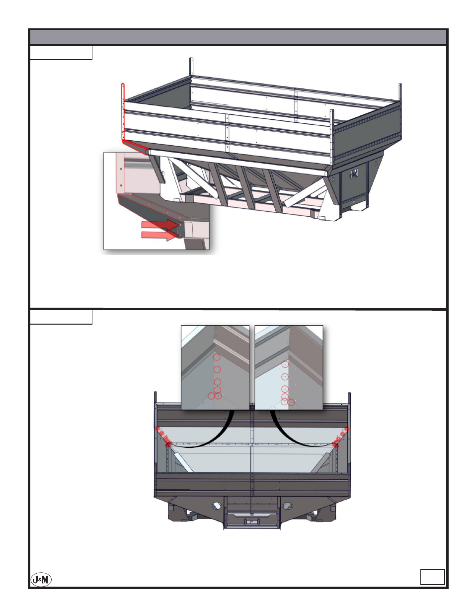
STEP - 12
STEP - 11
M12 x 25MM
M12 x 25MM
Install the Opposite Dumpside Rear Corner and the Rear Corner Gusset. Use (16) 8.8 M10 x
25 MM serrated flange hex head bolts and (16) M10 serrated flange hex head nuts to attach the
corner and gusset to the shell body. Use (2) 8.8 M12 serrated flange hex head bolts and (2) M12
serrated flange hex head nuts to finish attaching the gusset to the shell body.
Tighten all of the bolts circled in the image above.
See also other documents in the category J&M Gardening equipment:
- 525-14W (31 pages)
- 750-16 (33 pages)
- 750-18 (34 pages)
- 1000-20 (31 pages)
- 1050-20 (37 pages)
- 1130-20 (36 pages)
- 1325-20 (36 pages)
- GC-24T Manual (39 pages)
- GC-31T Manual (38 pages)
- GRAIN CARTS Leaner Setup (18 pages)
- 250-7S (12 pages)
- 385SD (13 pages)
- 440SD (13 pages)
- 680SD (13 pages)
- 750SD (13 pages)
- 275ST (62 pages)
- 375ST (62 pages)
- 500ST (51 pages)
- 375ST Remote (24 pages)
- 500ST Remote (23 pages)
- PRO 450 (31 pages)
- TF2 (37 pages)
- HT-974 (16 pages)
- TB-3500-6000A (20 pages)
- TB-3500-6000H (21 pages)
- TB-8000H-42 (20 pages)
- 4WS15 (27 pages)
- 750-14 (29 pages)
- 818 (35 pages)
- 875-16 (29 pages)
- 1000-20S (34 pages)
- 1050-18S (28 pages)
- 1050-18D (22 pages)
- 1050-20S (33 pages)
- 1050-20D (33 pages)
- 1050-22S (23 pages)
- 1050-22D (14 pages)
- 1051-22S (33 pages)
- 1051-22D (33 pages)
- 1075-18R (23 pages)
- 1075-22R (23 pages)
- 1325-20S (33 pages)
- 1325-20D (33 pages)
- 1325-22S (23 pages)