Slip control, Speed measurement, Slip control example – MoTeC MDC2 User Manual
Page 5
MoTeC MDC2
3
Functionality
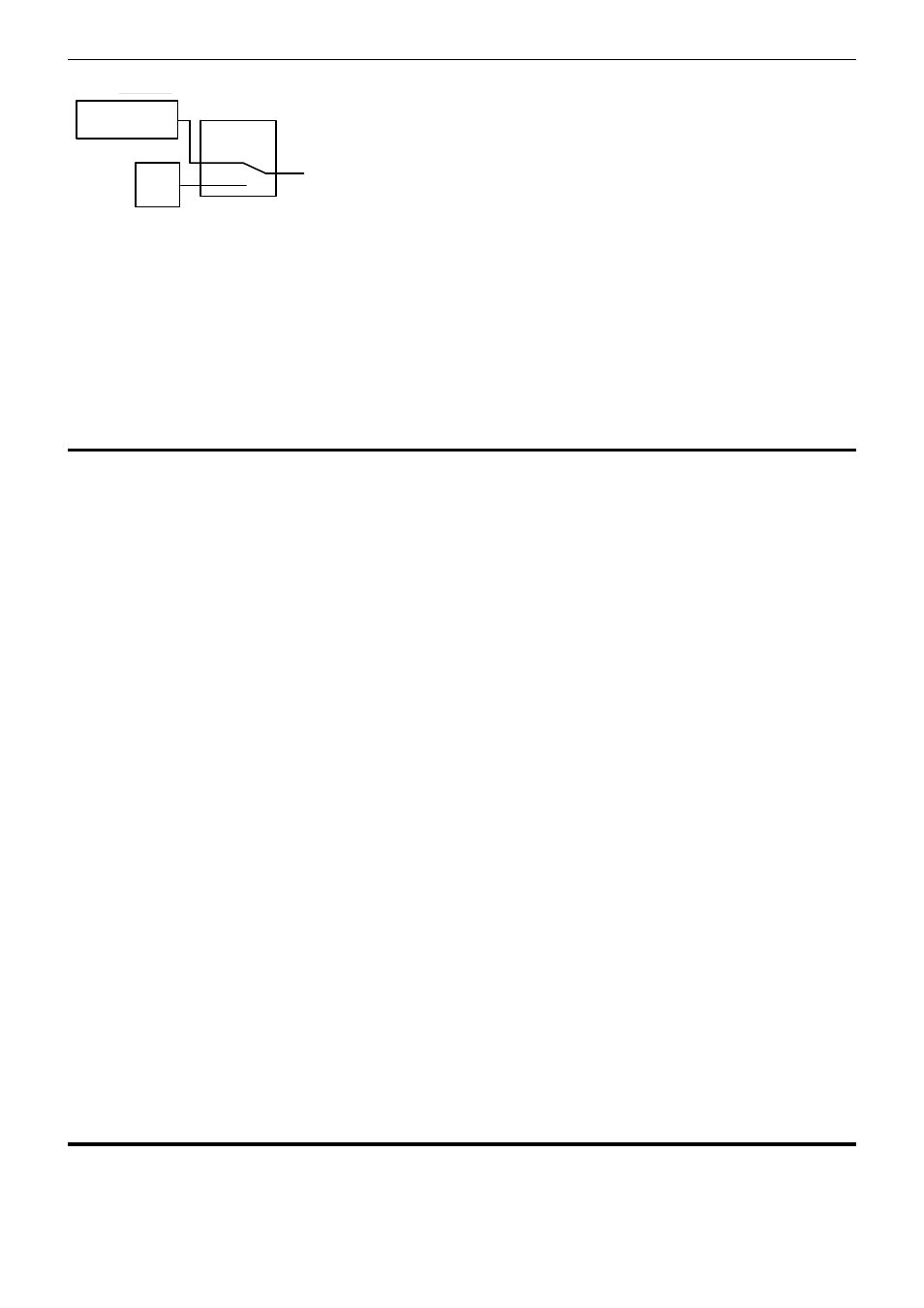
The lock percentage for the constant lock mode is determined according to the following strategy:
% lock
Handbrake
ON
OFF
0%
Lock
Constant
lock %
The constant lock % is equivalent to the maximum lock achieved by the Mitsubishi factory AYC / ACD controller.
The lock percentage is always 0% in the 0% lock mode.
Note:
The handbrake status is ignored during a handbrake start from 0km/h – See Handbrake Override below.
For information on configuring the user modes see the MDC2 Manager section.
Slip Control
The slip control strategy detects slip (i.e.: rear speed ≠ front speed) and increases diff lock to maintain slip close
to the value specified in the Desired Slip table. The Desired Slip table specifies the value above which additional
diff lock will be applied, according to the slip control setup parameters.
The calculation of lock percentage for slip control is determined by the Slip Control Range and Max Slip Control
Lock
parameters which apply to all user modes.
The following algorithm determines the %lock for slip control. The desired slip is the output from the Desired Slip
table.
IF Rear Speed > Front Speed
THEN Measured Slip = Rear Speed – Front Speed
ELSE Measured Slip = Front Speed – Rear Speed
Slip Control Factor
= (Measured Slip – Desired Slip) / Slip Control Range
Constrain Slip Control Factor to the range 0 to 1
Slip Diff Lock
= Slip Control Factor * Max Slip Control Lock
NOTE: Slip is specified as speed difference between front and rear wheels, not as a ratio of the speeds.
The addition of the calculated slip diff lock percentage is shown in the lock percentage strategy above.
Slip control example
Max slip control = 10% lock
Slip control range = 20 km/h
Desired slip (from Desired Slip table) = 10km/h
For a measured slip of 15km/h, slip diff lock = ((15 – 10) / 20) * 10 = 2.5%
For a measured slip of 30km/h or above, slip diff lock = 10%
For information on configuring the slip control parameters, see Setup | User Modes in the MDC2 Manager
section.
Speed Measurement
The four wheel speeds are received on the CAN bus from the ABS module, or the four wheel speed sensors can
optionally be wired directly to the MDC2. If the ABS module is removed, the sensors must be directly connected
to the MDC2.