Appendix b – mdc2 pinout and links, Mdc2 connector pinout, Motec mdc2 14 appendices – MoTeC MDC2 User Manual
Page 16
MoTeC MDC2
14
Appendices
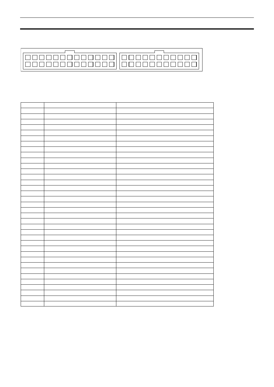
Appendix B – MDC2 Pinout and Links
MDC2 Connector Pinout
2
15
3
16
4
17
5
18
1
14
6
19
7
20
8
21
9
22
10
23
11
24
12
25
13
26
52
31 32 33
42
51
34
43
35
44
36
45
37
46
38
47
39
48
40
49
41
50
The 26 pin MDC2 connector connects to the factory wiring loom.
The 22 pin MDC2 connector offers inputs and outputs for custom wiring such as direct wheel speed inputs.
Pin Function
Notes
1
ACD valve output
Switched positive output
4
CAN-HI (main CAN bus)
5
CAN-LO (main CAN bus)
6 5V
Aux
7
Hydraulic pressure sensor
8 0V
9
CAN-HI (secondary CAN bus)
To Yaw/G sensor
10
CAN-LO (secondary CAN bus)
To Yaw/G sensor
11
Steering wheel mode switch
13 Battery
-
16 Battery
+
19 0V
20
Pump relay output
Switched positive output
31 0V
32
Front left speed sensor input
Magnetic or Hall
33
Front right speed sensor input
Magnetic or Hall
34
Rear left speed sensor input
Magnetic or Hall
35
Rear right speed sensor input
Magnetic or Hall
36
Brake pedal input
12V when brakes applied
37
Handbrake input
0V when handbrake ON
38
Throttle position sensor input
0-5V
39 5V
Aux
40 0V
41 0V
42
Battery +
Output for auxiliary equipment
43
Battery +
Output for auxiliary equipment
44 0V
45 0V
46
CAN-HI (main CAN bus)
47
CAN-LO (main CAN bus)
48
SNOW light output
Active low
49
GRAVEL light output
Active low
50
TARMAC light output
Active low
51 0V
52 0V