DE-STA-CO P1700 User Manual
Page 7
5
SECTION 2: Overview
The sketches contained in this document are for illustrative purposes only. They are intended to
represent the component but may not be shown to scale. The various models may be different than
shown, depending upon options chosen or the particular configuration of a unit.
2.1.
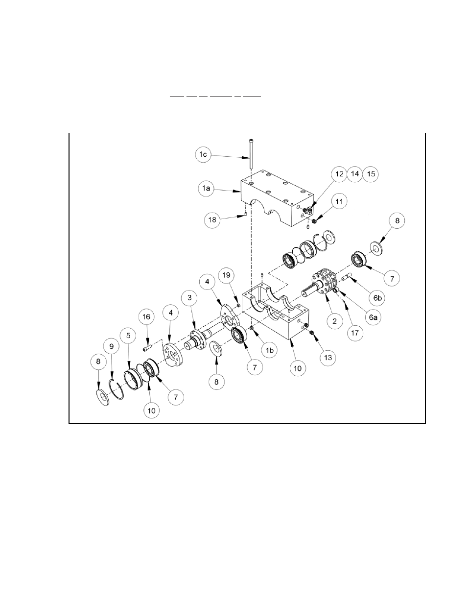
ParaDex Location Map
FIGURE 1
ParaDex Parts List
1.
Housing
1a. Housing Halves
1b. Threaded Inserts – Nutsert
1c. Socket Head Cap Screw
(5” Long)
2.
Output Shaft
3.
Cam Shaft
4.
Cams
5.
Eccentric Bushings (2)
6a. Cam Follower Bearing
6b. Cam Follower Stud
7.
Double Row Ball Bearing (4)
8.
Shaft Seals (4)
9.
Snap Ring (2)
10. “O” Ring (2)
11. Oil Gage
12. Vent
13. Pipe Plug (2)
14. Adapter
15. 90° Street Ell
16. Socket Head Cap Screw
(Cam)
17. Set Screw
18. Dowel Pin
19. Threaded Insert - Nutsert