BVA Hydraulics J13300 User Manual
Page 3
3
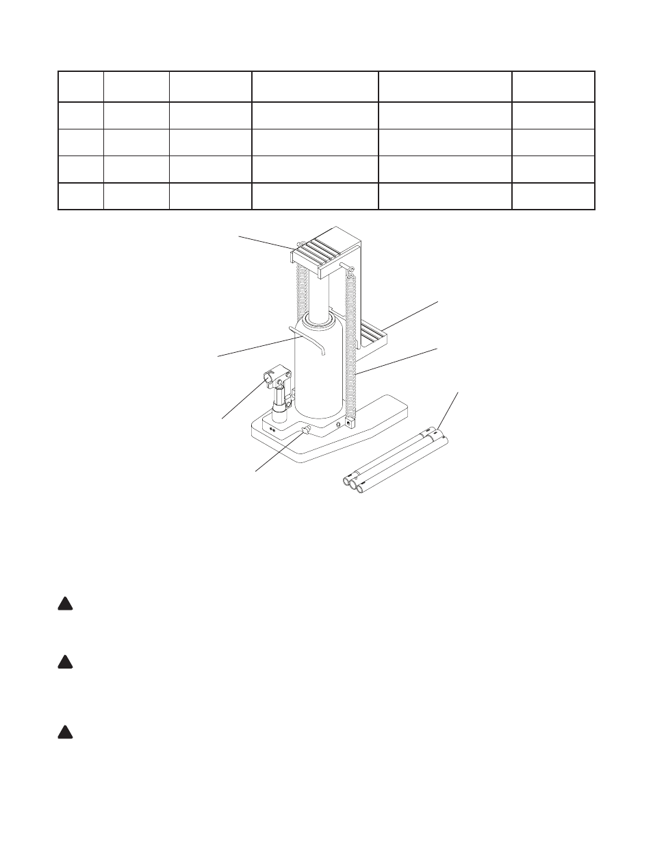
Figure 1 - Typical Toe Jack Components
SPECIFICATIONS
Model
Capacity
Base Size
(l" x w")
Toe Saddle
Min. / Max Height
Head Saddle
Min. / Max. Height
Hydraulic Lift
J13060
3 Ton
8-5/8 x 7-1/2
5/8" / 5-3/4"
9" / 14-1/8"
5-1/8"
J13120
6 Ton
11 x 7-1/2
7/8" / 6"
10-1/2" / 15-5/8"
5-1/8"
J13200
10 Ton
11-5/8 x 9-1/4
1-1/8" / 6-1/4"
11" / 16-1/8"
5-1/8"
J13300
15 Ton
12-1/2 x 10-3/4
1-1/8" / 6-5/8"
13-1/8" / 18-5/8"
5-1/2"
OPERATION
Raising the Ram Plunger
1. Use the handle to engage and turn the release valve clockwise until firm resistance is felt to further thread engagement.
2. Pump until load reaches desired height.
Immediately secure with appropriately rated mechanical devices.
It is recommended you follow the load with cribbing and blocking where practical.
WARNING: Never allow personnel to work or pass under a load until the load is secured by cribbing, blocking, or other
mechanical means.
Lowering
WARNING: Clear all personnel and tools before lowering load. Control the rate of descent of the load at all times. The
more you open the release valve, the faster the load will descend.
1. Use the manufacturer's provided operating handle to engage and slowly turn the release valve counter-clockwise, but no more
than 1 turn.
WARNING: If the operating handle is damaged, operates abnormally, or will not positively engage the release valve,
immediately discontinue use of the jack until a manufacturer's replacement handle assembly can be acquired.
2. Push ram down and handle sleeve in to reduce exposure to rust and contamination after removing jack from under load.
!
!
!
Handle Sleeve
Handle
Head Saddle
Toe Saddle
Release Valve
Carry Handle
Oil Filler Plug/Screw (ref.
Parts illustration for location)
Return Spring