Bray 63 N4 Series User Manual
Page 3
All information herein is proprietary and confidential and may not be copied or reproduced without the expressed written
consent of BRAY INTERNATIONAL, Inc.
The technical data herein is for general information only. Product suitability should be based solely upon customer’s detailed
knowledge and experience with their application.
SERIES 63 N4 Operation & Maintenance Manual
Manual Number OM-63/N4-001
Date: September 2, 2010 Page 3 of 5
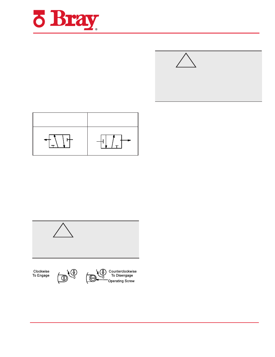
4-Way Dual Solenoid Operation
• Solenoid A Last Energized: Flow is from
pressure port 1 to port 2 and from port 4 to
port 5. Port 3 is closed. Slight pilot exhaust
apparent when solenoid A is de-energized.
• Solenoid B Last Energized: Flow is from
pressure port 1 to port 4 and from port 2 to
port 3. Port 5 is closed. Slight pilot exhaust
apparent when solenoid B is de-energized.
4-Way Dual Solenoid (5/2)
Manual Operator (See Figure 1)
Manual operator provides manual operation
when desired or during an electrical power out-
age. To engage manual operator, rotate screw
clockwise as far as possible to “1”. Valve will
now be in the same position as when the sole-
noid is energized. To disengage manual op-
erator, rotate screw counterclockwise as far as
possible to “0”.
CAUTION
To prevent malfunction be sure to turn screw
counterclockwise to “0” before operating
valve electrically.
Figure 1. Manual Operator (partial view)
Installation
WARNING
Check nameplate for correct catalog number,
pressure, voltage, frequency, and service. Never
apply incompatible medium or exceed pressure
rating of the valve. Installation and valve main-
tenance to be performed by qualified personnel.
Future Service Considerations
Provision should be made for performing seat leak-
age, external leakage, and operational tests on the
valve with a nonhazardous, noncombustible fluid.
NOTE: For temperatures below 32°F (0°C)
moisture-free air must be used.
Positioning
Valve may be mounted in any position.
Flow Selection and Mounting (See Figure 2)
Two flow plates are provided with each valve.
Flow plates are marked (3/2) for 3-way or (5/2)
for 4-way. See Figure 2 for proper orientation of
flow plate, gaskets, mounting screws and locating
set screw. Then proceed as follows:
1. If required, install locating set screw using a 2
mm hex key wrench.
2. Install Port 2 and Port 4 gaskets and flow gas-
ket on flow plate.
3. Position flow plate and solenoid valve on
actuator. Then install two socket head cap
screws in offset center holes on either side.
Hand thread screws a few turns into actuator.
Then tighten screws evenly using a 4 mm hex
key wrench.
Piping
There is pilot exhaust from the top of the solenoid
when the solenoid is de-energized. The pilot ex-
haust may be connected to the main exhaust if the
air or inert gas cannot be exhausted directly to the
atmosphere. An exhaust protector is provided in
the top of the plugnut/core tube assembly to pre-
vent debris from entering pilot exhaust.
Solenoid “A”
Last Energized
Solenoid “B”
Last Energized
B
A
Pilot
Exh.
Pilot
Exh.
4
2
3 1 5
B
A
Pilot
Exh.
Pilot
Exh.
4
2
3 1 5
!
!