Configuration diagrams, Maintenance, Troubleshooting – Bray 62 Series User Manual
Page 2: Tools required
SERIES 62 Solenoid Pilot Valve
Operation & Maintenance Manual
Manual Number OM-62-001 • Date: March 24, 2014 8:28 AM • Page 2 of 2
All information herein is proprietary and confidential and may not be copied or reproduced without the expressed written consent of BRAY INTERNATIONAL, Inc.
The technical data herein is for general information only. Product suitability should be based solely upon customer’s detailed knowledge and experience with their application.
Before work, switch off the electrical power supply to
de-energize all components
Depending on the voltage, electrical components must be
provided with a ground/earth connection and satisfy local
regulations and standards.
The Bray Series 62 solenoid valve is designed for contin-
uous duty service. To avoid any possibility of damage or
injury do not touch the solenoid which can become hot
under normal operating conditions. If the solenoid valve
is easily accessible, the installer must provide protection
against accidental contact.
Maintenance.
Prior to any maintenance work or returning to operation, shut
off supply to the pilot solenoid valve, depressurize and vent
the valve in order to prevent injury or damage.
Cleaning: maintenance of the valve depends on the oper-
ating conditions. They must be cleaned at regular intervals.
During servicing, the components must be checked for ex-
cessive wear. If operation cycle is slow, ensure proper supply
pressure and that there is no unusual noise or leak detected.
Sound emission: the sound emission depends on the appli-
cation, supply medium and nature of the equipment used.
Exact determination of the sound level can only be carried
out by the user having the valve installed in their system.
Preventive maintenance: Operate the pilot solenoid
valve monthly to check function. Should any difficulties or
questions arise during installation and maintenance, please
contact a Bray representative.
Troubleshooting
:
Incorrect supply pressure: check the supply pressure,
Minimum air supply – 22 psi (1.5 bar)
Maximum air supply - 130 psi (9 bar)
Tools Required
Phillips (cross drive) screwdriver, to assemble and disassem-
ble solenoid coil to pilot valve
Small flat blade screwdriver, to engage disengage manual red
close button.
5/32”or 4mm hex screwdriver (Allen wrench), to fasten the
solenoid pilot valve to pneumatic actuator.
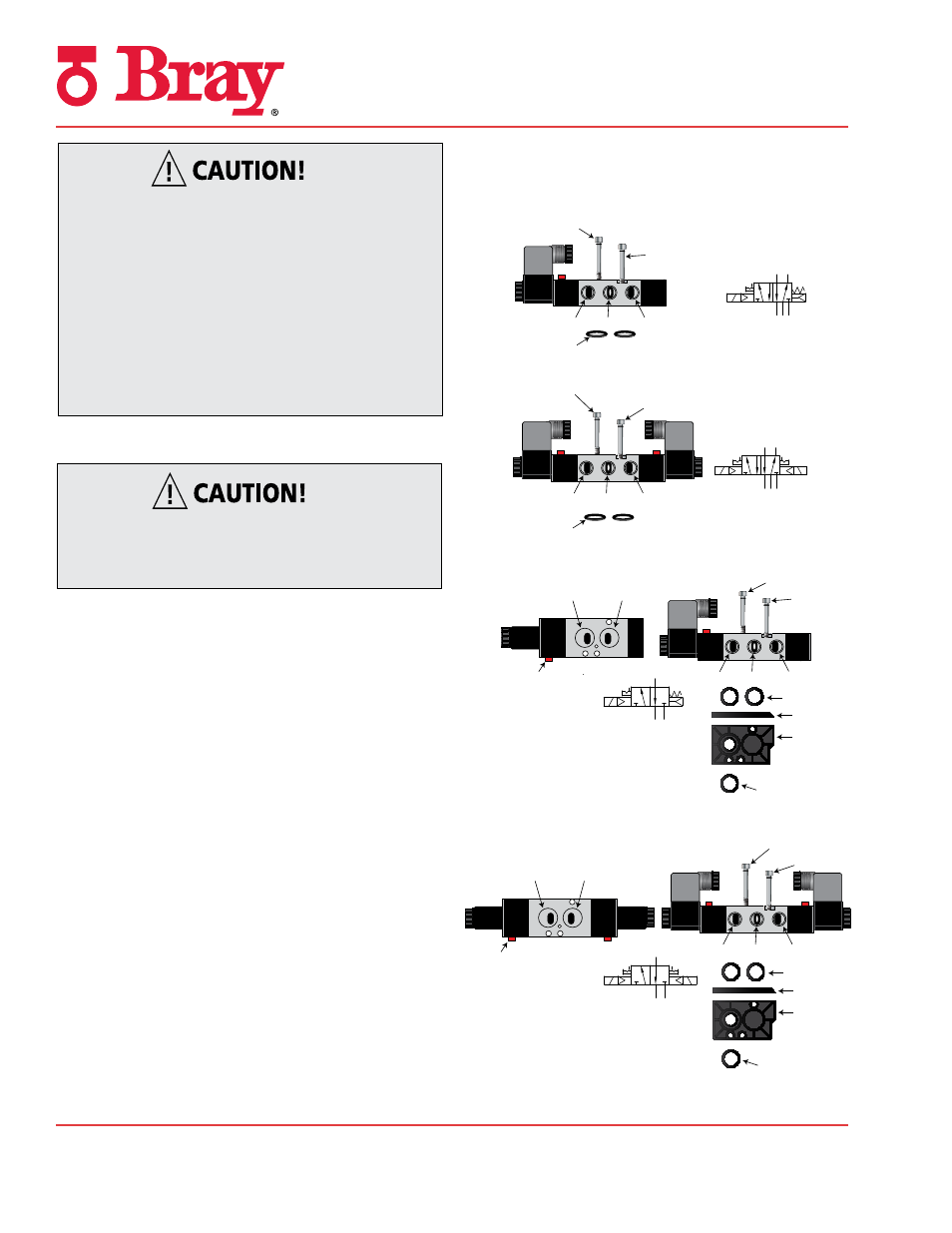
Configuration Diagrams
Figure 3
3/2 for Single Acting/Spring Return Valve
(Single Coil)
Mark
3 1
4
Figure 4
3/2 for Single Acting/Spring Return Valve
(Double Coil)
Mark
2
1
3
Figure 1
5/2 for Double Acting Solenoid Valve
(Single Coil)
Mark
2
4
5
1
3
Figure 2
5/2 for Double Acting Solenoid Valve
(Double Coil)
Mark
3 1 5
4
2
Port 2
Port 4
Manual Override
Port 1
Port 3
Port 5
Port 2
Port 4
Manual Override
Port 1
Port 3
Port 5
Port 1
Port 3
Port 5
Port 1
Port 3
Port 5
O-Rings
O-Rings
Long Screws
Short Screws
Long Screws
Short Screws
Long Screws
Short Screws
Long Screws
Short Screws
O-Rings
Air Flow Plate Side
Air Flow Plate
O-Ring
O-Rings
Air Flow Plate Side
Air Flow Plate
O-Ring