Model 296, Specifications – Atec Wavetek-295-296 User Manual
Page 2
6
Model 296
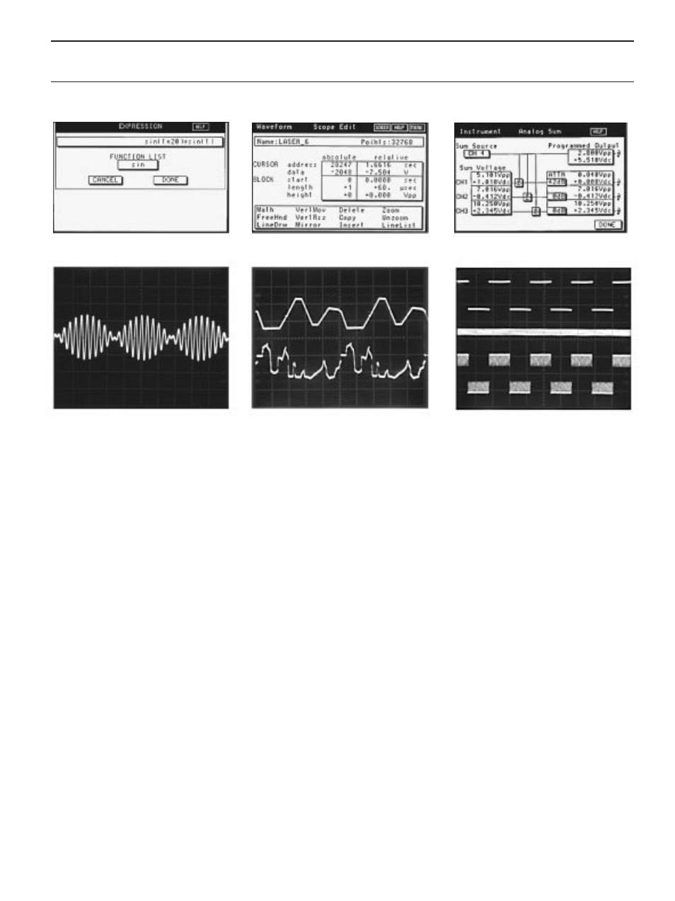
Typical math expression screen.
Amplitude modulated signal generated by the
expression shown on the math expression
screen above.
Scope Edit screen.
Scope shows waveforms created with Line
Draw/Line List (top) and Freehand Draw
(bottom).
Summing screen.
Scope illustrates summing. Top: Clean square
wave. Middle: Noise. Bottom: Summed
waveform (square wave with noise).
available.
An internal memory of 60 kB is provided
for storing the waveforms you create. Storing
waveforms created or captured elsewhere is
no problem either. Simply download
waveforms over the GPIB or RS-232
interface or through the standard 3.5-in disk
drive. You can download waveforms
generated in Wavetek’s WaveForm DSP
arbitrary waveform creation software or
directly from a DSO (with Option 005). Or
use the disk drive to load ASCII files
generated from spreadsheet programs such
as Microsoft Excel
®
or Borland’s Quattro
Pro
®
.
Use Math Expressions. You can create
waveforms with mathematical precision by
entering math expressions using the
numerical keys on the front panel.
Use Line Draw/Line List and Freehand
Draw. For waveforms with straight lines, as in
pulse or digital applications, Line Draw
allows you to use the mouse to draw the
lines on an oscilloscope. Lines may also be
created using Line List, which allows you to
enter the vertices of each line with ampli-
tude and time value. For other kinds of
applications, Freehand Draw gives the
flexibility of using the mouse to draw a
waveform on the oscilloscope in much the
same way as with a pencil on paper. This
makes tasks like inserting spikes on
waveforms easy.
Sum Multiple Channels to Create Complex
Waveforms. With the internal analog
sumbus, you can sum waveforms from two
channels together and output the sum as a
complex or modulated waveform. The
optional high voltage and external summing
module allows three channels and an
external signal to be summed.
Create Long, Complex Waveforms with
Linked Sequence Operation. Up to 4,096
waveforms can be linked together with the
Model 296. Up to 4 waveforms can be
linked together with the Model 295. Loop
count and advance conditions for each
waveform are user programmable.
Trigger Operation. Each channel has its
own internal trigger generator and external
trigger input. Multiple channel triggering
and versatile interchannel triggering are also
provided.
More Tools Make Editing Easy. Models
296 and 295 give you easy ways to modify
waveforms you’ve created. For example, you
can copy and insert portions of existing
waveforms, move individual waveform
points, and increase or decrease the
amplitude of all or part of the waveform.
Digital Output (296 only). Each channel
provides a 16-bit digital output program-
mable to 50 MHz.
Specifications
NOTE: Specifications apply after a 20-minute warm-up.
Standard Waveforms
Sine, square, triangle, pseudo-random noise,
positive ramp, negative ramp, positive haversine,
negative haversine, sin x/x and DC.