Serial triggering and analysis (optional), Serial triggering, Bus display – Atec Tektronix-DPO3000 Series User Manual
Page 7: Bus decoding, Event table, Search
Mixed Signal Oscilloscopes — MSO3000 Series, DPO3000 Series
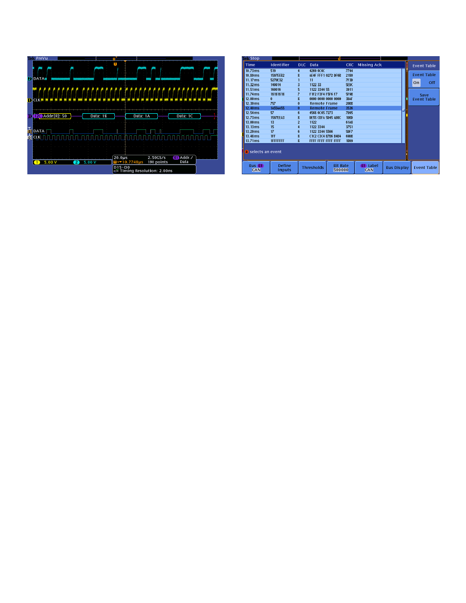
Triggering on a specific data packet going across an I
2
C bus. The yellow waveform is
clock and the blue waveform is data. A bus waveform provides decoded packet content
including Start, Address, Read/Write, Data, and Stop.
Serial Triggering and Analysis (Optional)
On a serial bus, a single signal often includes address, control, data, and
clock information. This can make isolating events of interest difficult. The
MSO/DPO3000 Series offers a robust set of tools for debugging serial
buses with automatic trigger, decode, and search for I
2
C, SPI, CAN, LIN,
RS-232/422/485/UART, and I
2
S/LJ/RJ/TDM.
Serial Triggering
Trigger on packet content such as start of packet, specific addresses,
specific data content, unique identifiers, etc. on popular serial interfaces
such as I
2
C, SPI, CAN, LIN, RS-232/422/485/UART, and I
2
S/LJ/RJ/TDM.
Bus Display
Provides a higher-level, combined view of the individual signals (clock, data,
chip enable, etc.) that make up your bus, making it easy to identify where
packets begin and end and identifying subpacket components such as
address, data, identifier, CRC, etc.
Bus Decoding
Tired of having to visually inspect the waveform to count clocks, determine
if each bit is a 1 or a 0, combine bits into bytes, and determine the hex
value? Let the oscilloscope do it for you! Once you’ve set up a bus, the
Event table showing decoded Identifier, DLC, DATA, and CRC for every CAN packet in
a long acquisition.
MSO/DPO3000 Series will decode each packet on the bus, and display the
value in hex, binary, decimal (LIN only), signed decimal (I
2
S/LJ/RJ/TDM
only), or ASCII (RS-232/422/485/UART only) in the bus waveform.
Event Table
In addition to seeing decoded packet data on the bus waveform itself, you
can view all captured packets in a tabular view much like you would see in
a software listing. Packets are time stamped and listed consecutively with
columns for each component (Address, Data, etc.).
Search
Serial triggering is very useful for isolating the event of interest, but once
you’ve captured it and need to analyze the surrounding data, what do
you do? In the past, users had to manually scroll through the waveform
counting and converting bits and looking for what caused the event. With
the MSO/DPO3000 Series, you can have the oscilloscope automatically
search through the acquired data for user-defined criteria including serial
packet content. Each occurrence is highlighted by a search mark. Rapid
navigation between marks is as simple as pressing the Previous (←) and
Next (→) buttons on the front panel.
www.tektronix.com
7