Atec Vanguard-CT7500 User Manual
Page 3
3
Breaker Initiate Features
A built-in solid-state initiate device is used to
operate a breaker from the CT-7500 S2. The
operational modes include Open, Close, Open–
Close, Close–Open, and Open–Close–Open.
Multiple operations, such as Open–Close and
Open–Close–Open, can be initiated by using
programmable delay time or by sensing a break-
er’s contact condition.
A built-in Hall-effect current sensor records
the Trip/Close current level and duration. The
breaker’s operate-coil current waveform dura-
tion (effectively, a performance "fi ngerprint" or
"current profi le") can be used as a diagnostic
tool for analyzing a breaker’s performance.
Computer Interface
The CT-7500 S2 can be computer-controlled via
its RS232C or USB interface. Windows® based
BreakerAnalysis software is provided with each
unit. Using this software, circuit-breakers can
be timed from the PC. Test records can be re-
trieved from the CT-7500 S2 and then stored on
the PC for future analysis and report generation.
Circuit-breaker test plans can also be created on
the PC and transferred to the CT-7500 S2. Ad-
ditionally, test records can be exported in Excel,
PDF, and XML formats for further analysis.
CT Input
One non-contact AC current sensor is used to
monitor circuit breaker on-line current for the
“on-line” timing mode.
Internal Test Record and Test
Plan Storage
Up to 150 test records can be stored in Flash EEPROM.
Test records can be retrieved and printed on the built-in
thermal printer, or they can be transferred to a PC via the
unit’s RS232C or USB interface.
Up to 99 circuit breaker test plans can be stored in Flash
EEPROM. Test plans are comprised of all circuit-breaker
performance specifi cations (stroke, velocity, and con-
tact time). A test plan can be used to immediately test
a circuit-breaker. A pass/fail report is then generated by
comparing actual performance with the specifi cations in
the stored test plan. Test plans can also be generated
on a PC and transferred to the CT-7500 S2 via the unit’s
RS232C or USB interface.
Diagnostic Capabilities
The CT-7500 S2 can perform diagnostics on its internal
electronics. Diagnostics can be performed to verify con-
tact cable connections and to test the travel transducer’s
electronics.
Built-in Thermal Printer
The CT-7500 S2’s built-in 4.5-inch wide thermal
printer can print the breaker contact analysis re-
sults in both tabular and graphic formats.
User Interface
The CT-7500 S2 features a back-lit LCD screen
(20 characters by 4 lines) that is viewable in
both bright sunlight and low-light levels. A rug-
ged, 16-key, membrane keypad is used to control
the unit.
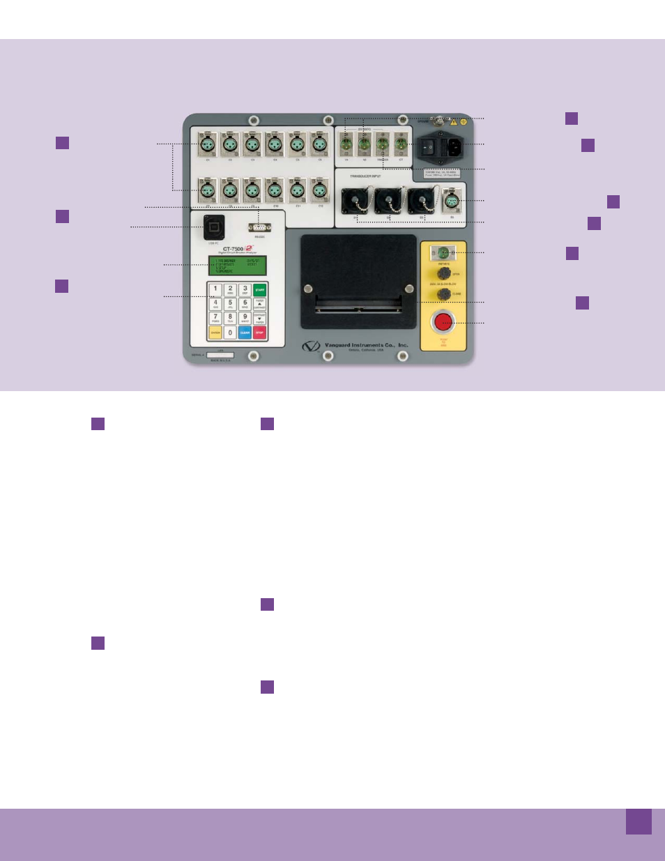
Contact Timing Channels
1
Digital Transducer Connectors
2
Resistor Type Transducer Connector
3
Voltage Input Channels
4
Breaker Initiate Output
5
5
USB PC Interface
RS-232C PC Interface
7
7
AC Clamp-on Current Probe
6
6
4.5" Wide Thermal Printer
8
8
9
Back-lit LCD Screen
(20 characters by 4 lines)
9
Rugged 16-key membrane
keypad
Breaker Initiate Arm Switch
CT-7500 S2 Controls & Indicators
Trigger Input Connector