Phase synchronization or add 600 ω output – Atec HP-Agilent-8904A User Manual
Page 8
8
. . . Phase synchronization
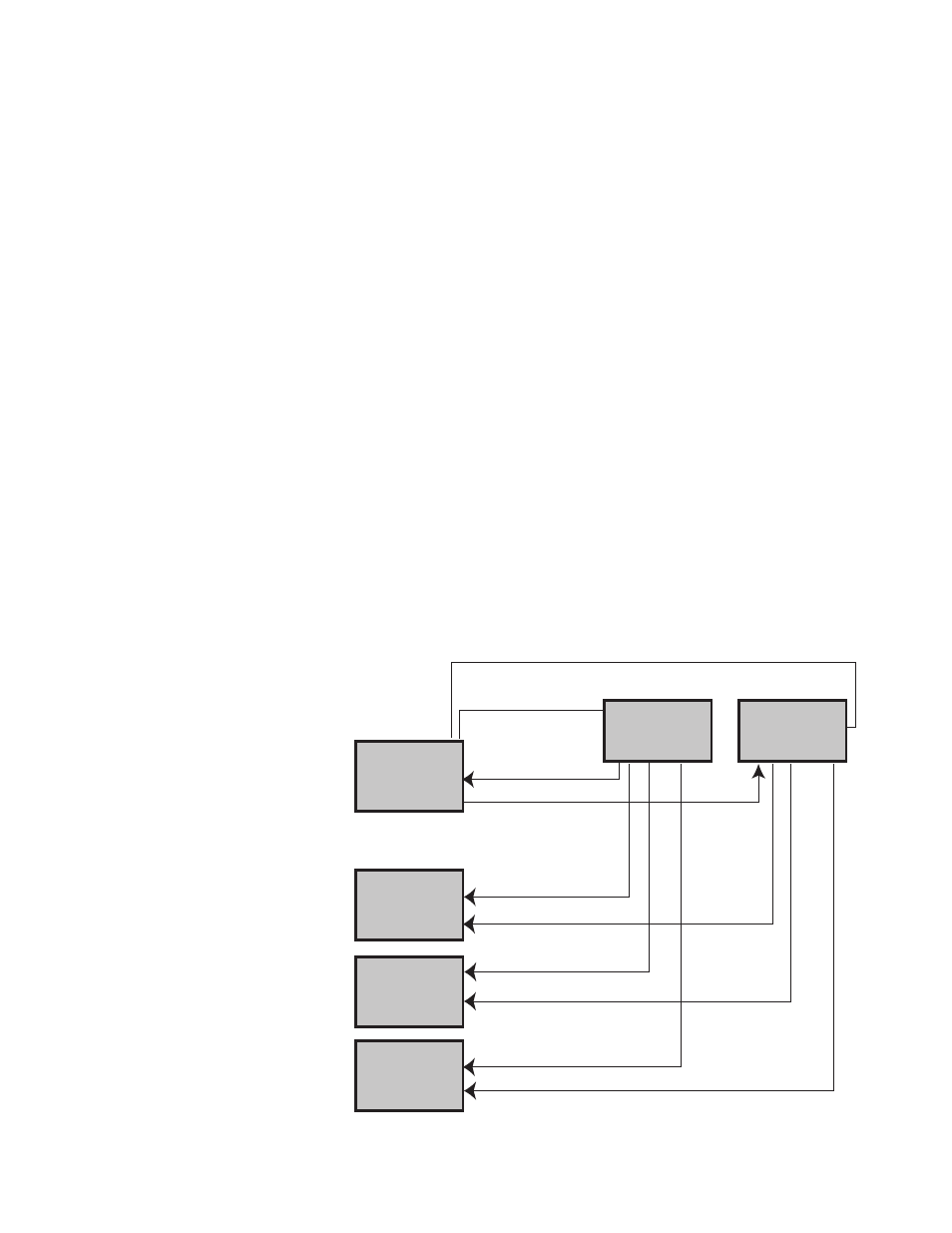
With Option 005, multiple 8904As can
be phase synchronized to provide more
than two channels of phase related
outputs. In the synchronous mode,
one unit is specified to be the “master”
and all others are designated “slaves.”
Two signals from the master unit (sync
clock and phase reset) are routed to
external power splitters which divide
the signals to the slave units. When a
phase reset command is issued from
the master, via the front panel or GPIB,
all units reset to their specified phase
relationships. In this mode all con-
nected units are phase locked and
will not drift relative to each other.
Whenever the frequency, destination,
or angle modulation amplitude are
changed on any of the units, a phase
reset must be issued on the master
unit to restore proper phase. In the
synchronous mode, the phase accuracy
from unit to unit is specified as an
additional 30 ns error for frequencies
from 0.1 Hz to 100 kHz. This yields a
total specification of the larger of
±0.1 degree or 60 nsec for the same
frequency range. Using low-loss power
splitters, up to eight units can be syn-
chronized for a total of 16 phase
related outputs if the units have
Option 002. If more signals are desired,
amplifiers can be inserted before the
power splitters to increase the number
of synchronized units. Because the
extra cables required for synchronous
operation use the mounting holes
normally reserved for rear panel out-
puts, Option 004 (rear panel outputs)
cannot be ordered with Option 005.
Option 005 solves many tough testing
problems by providing a high perform-
ance yet low cost solution to generat-
ing many phase related signals. For
example, testing three phase power
line devices requires the generation
of three voltage and three current
waveforms which are phase related.
With Option 005, three 8904As with
Option 002 and 005 can be used to
generate the required signals. Acoustics
and sonar work also require large
numbers of phase related signals. With
Option 005, the 8904A can be used to
provide a cost effective solution for
these demanding applications.
Or add 600
Ω
balanced output
Option 006 replaces the standard 50
Ω
electronic floating output (output one
only) with a transformer coupled 600
Ω
output, This balanced, fully floating
output delivers higher power into
600
Ω
loads than the standard 50
Ω
output. The maximum signal level is a
full 10 volts rms into a 600
Ω
load (20
volts rms open circuit). The Option 006
output is specified for sinewaves only
and covers the frequency range of
30 Hz to 100 kHz.
Output frequencies above 100 kHz are
available up to 200 kHz with a typical
rolloff of –4 dB at 200 kHz. Option 006
is ideal for applications requiring true
balanced operation or the higher signal
levels commonly required in 600
Ω
audio systems. Because of the band-
limited nature of a transformer cou-
pled output, Option 006 cannot pass dc
or low frequency signals, and causes
waveform distortion when passing
square or ramp waveforms. The trans-
former adds little distortion above
300 Hz preserving the excellent spec-
tral purity of the standard 8904A. The
Option 006 output also has degraded
phase linearity compared to the excel-
lent phase linearity of the standard
50
Ω
output. Option 004, rear panel
outputs is not available when Option
006 is ordered.
Phase synchronization or add 600
Ω
output
8904A Master
8904A Slaves
Phase Reset
Sync Clock
Sync Clock Output
Phase Reset Output
Phase Reset In
Sync Clock In
Phase Reset In
Sync Clock In
Phase Reset In
Sync Clock In
Phase Reset In
Sync Clock In
Low-loss power splitters*