And you get complex signal generation – Atec HP-Agilent-8904A User Manual
Page 5
5
VOR/ILS
VOR (VHF Omni Range) signals are
used by modern aircraft for naviga-
tion. To create accurate VOR com-
posite signals, a generator must have
precise frequency modulation and
extremely accurate phase settability.
Agilent 8904A Option 001 meets these
needs easily with mathematically cal-
culated frequency modulation and the
repeatability of digital phase offset
control. For VOR, channel B is used
to frequency modulate channel A,
while channel C is summed with the
modulated channel A. The bearing
angle can then be changed by altering
the relative phase of channel C. The
minimum bearing angle resolution is
0.1 degree. Since the entire VOR com-
posite waveform is “calculated” in real
time by the Digital Waveform Synthesis
IC, the 8904A Option 001 can deliver
typical bearing accuracy on the order
of ±0.05 degrees. This state-of-the-art
performance is repeatable and drift
free unlike older technology analog VOR
generators. ILS (Instrument Landing
System) composite signals can also be
generated with digital accuracy with
the 8904A Option 001.
Audio testing
With Option 001, the 8904A can gen-
erate many different types of test sig-
nals used in audio applications. By
summing or modulating with the four
internal channels, the 8904A can gen-
erate intermodulation test signals
which conform to international stan-
dards. CCIF twin-tone, DIN, and
SMPTE intermodulation test signals
can be created with the 8904A. Typical
residual intermodulation distortion is
less than –70 dB. With independent
control of all four internal synthesiz-
ers, almost any type of IM test signal
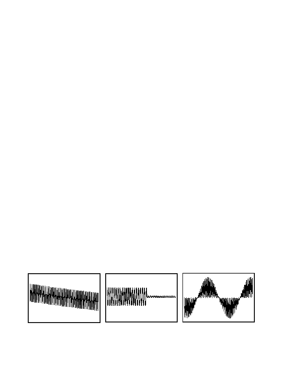
can be generated. Another complex
signal often used to test amplifier
power reserves is the IHF Dynamic
Headroom test signal. The 8904A can
generate this signal with synthesizer
precision, low distortion, and exact
timing. In fact, any sinewave burst
signal can be created which will be
glitch free with phase continuous
transitions within the frequency reso-
lution of the 8904A (0.1 Hz). Another
useful signal is a phase-continuous
linear sweep. By using a ramp wave-
form to frequency modulate channel
A, a linear phase continuous sweep
can be created. Sweep time can be
varied from 10 seconds (ramp at 0.1 Hz)
to 20 microseconds (ramp at 50 kHz).
Special functions can be set which will
reverse the modulating ramp waveform
to produce sweeps which change the
sweep direction.
FM stereo mode
In conjunction with an RF signal gen-
erator, the 8904A Option 001 can gen-
erate the signals required to test com-
mercial FM broadcast stereo receivers.
The FM stereo mode included with
Option 001 transforms the 8904A into
a dedicated FM stereo encoder. Single
keystrokes control the audio test tone
frequency, composite signal level, test
signal mode, pilot on/off, and pilot
level in terms of % of composite level.
Test signal modes include Left=Right,
Left=– Right, Left Only, and Right Only.
The pilot tone amplitude, frequency
and phase, as well as subcarrier fre-
quency are fully adjustable. Audio
test tone frequency can be set from
20 Hz to 15 kHz in 0.1 Hz increments.
Three pre-emphasis curves ensure
compliance with all international stan-
dards: 25 µsec, 50 µsec, and 75 µsec.
Digital synthesis combined with superb
analog performance yields typical
stereo separation of greater than 65 dB
over the full 20 Hz to 15 kHz audio
bandwidth. The digital nature of the
stereo test signals generated by the
8904A eliminates such signal by-prod-
ucts as subcarrier leakage and pilot
tone/subcarrier phase error found in
analog stereo encoders.
. . . And you get complex signal generation . . .