Power, Analyzer, Harmonics – Atec Fluke-39-41B User Manual
Page 2: 39/41b power meter glossary
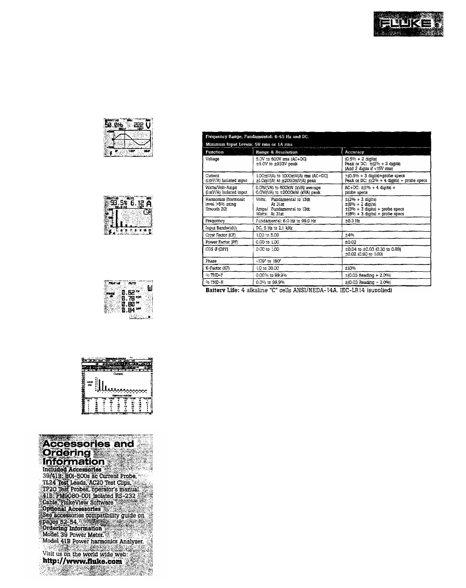
Fluke 39 Power Meter/4113
Power
Harmonics
Analyzer
Applications
VOLTS
Display
One cycle of
the fundamental
waveform and
its frequency.
Instantaneous voltage at cursor position.
Application
Detecting flat-topped voltage caused by
current harmonics, and notching caused
by SCR switching.
AMPS
Display
%-fundamental or
%-rms, rms value,
frequency, and phase
angle of fundamental
or harmonic currents (up to 31st(,
as selected by cursor from bar graph.
Application
Identifying .sources of harmonic currents.
Obtaining data for designing, specifying
or sizing transformers, filters, etc.
WATTS
Display
Watts, volt-amps,
power factor (total)
and displacement
power factor (COS 0)
. i
of single or three-phase power.
Application
Identifying displacement (COS
0)
versus
total power factor. Determining proper
power-factor correction methods.
Using the
included
PlukeView
418 software
you can
upload and
download
measurements
and setups to
a Windows or DOS based PC.
48 hours typical (continuous)
Shock & Vibration: Per MIL-T-28800, Class 3
Case: Drip-Proof and Dust-Proof per IEC, IP 52
Size: 234 mm L x 100 mm W x 134 mm D
Weight: 0.9 kg
One-Year Warranty
39/41B Power Meter Glossary:
DPF
Displacement Power Factor (COS 0). DPF is used to measure the effect o€ inductive
( motor, transformer( and capacitive loads on the efficiency of an ac distribution system. Such loads
have a reactive component (see VARs) which must be taken into account when sizing system
capacity, but they are still linear loads (current is drawn as a sine wave). DPF therefore does not
include the effect of non-linear harmonic currents, However, a low
DPF
will often result in extra
demand charges by utilities.
PF
Power Factor or Total Power Factor. Active Power divided by Apparent Power. PF is a
measurement of the efficiency of an ac power transmission and distribution system, including the
effects of harmonics (as well as VARs). Harmonic currents cause PF to be lower than DPF.
%
THD-F
Percent Total Harmonic Distortion-Fundamental reference. This reading
represents the ratio of the harmonic components of voltage lot current) to the voltage (or current)
of the fundamental alone. All measurements are true-rms.
O/oTHD-R
Percent Total Harmonic Distortion-HMS reference. This reading represents the
ratio of the harmonic components of voltage (or current) to the total voltage (or current), including
the fundamental and all harmonics. All measurements are true-rns.
( k)W
( kilo) Watts. Active power, also known as Real/True Power. Watts measure that portion of
electrical power which does work, which by definition includes heat losses. Utility charges are
based on Watts.
( k)VA
( kilo) Volt-Amperes. Apparent power. VA is computed by taking the product of the rms
values of voltage and current, It is a measure of the total electrical power capacity of a distribution
system or component equipment. In addition to Watts, it includes the contributions of VARs and
harmonic currents. This term is of interest because utility and facility engineers must size their
system equipment in VA, in effect providing the current-carrying capacity to handle the worst-
case situation.
(k)
VAR
( kilo) Volt-Amps Reactive. Reactive Power. VARs are the reactive component of VA
( Apparent Power), caused by a phase shift between ac current and voltage in inductors (coils) and
capacitors. In inductors, current lags voltage (in time), while in capacitors, current leads voltage.
VARs are typically first present in a distribution system as a result of inductive loads such as
motors, reactors and transformers. VARs are then used in sizing power factor correction
capacitors, which are used to offset the effects of these inductive loads.