Atec Solar-6220-1A User Manual
Page 4
AN622001 (continued)
radiation. The current probe was somewhat
better than the LISN for measurements below
150 KHz and above 25 MHz but, even so, the
technique was not very sensitive at the lower
frequency end of the spectrum.
A young Boeing EMI engineer named Frank
Beauchamp was the first to apply the current
probe to wideband measurements from 30 Hz to
20 KHz. He was smart enough to realize some of
the problems in this range so he incorporated the
sliding current probe factor into the method of
measurement he spelled out in the Minuteman
Specification, GM-07-59-2617A. The test method
required that the probe factor existing at 20 KHz
should be used for obtaining the wideband
answer in terms of “per 20 KHz” bandwidth. This
meant that the specified limit was not a constant
throughout the 20 KHz bandwidth, but was
varying as the inverse of the probe factor. A very
sensible solution at the time. Regrettably, later
specifications did not follow this lead.
When later EMI specifications extended the need
for measurement of EMI currents down to 30 Hz
without taking into account the sloping probe
factor, the problem of probe sensitivity became
critical. Attempts to compensate for the poor
current probe response at low frequencies by
using active element suffer from dynamic range
difficulties and the possibility of overload.
This led to another way of “skinning the cat,” with
the aid of the Audio Isolation Transformer already
available and in use for susceptibility testing.
The technique described in the following
paragraphs indicates how to obtain considerably
greater measurement sensitivity for conducted
narrowband EMI currents and a means for obtain-
ing a flat frequency characteristic without the use
of active elements for broadband or “wideband”
EMI current measurements.
BASIC CONCEPT
The application described herein has grown out
of a suggestion by Sam Shankle of Philco Ford in
Palo Alto. He and his capable crew first tried this
scheme using H-P Wave Analyzers as the associ-
ated voltmeter. Our work with the idea has
concentrated on conventional EMI meters with
50 ohm inputs.
Basically, the test method consists of using the
secondary (S) of the Solar Type 6220-1A Audio
Isolation Transformer as the pickup device.
The transformer winding normally used as the
primary (P) is used as an output winding in this
case. The method provides a two-to-one step up
to further enhance the sensitivity.
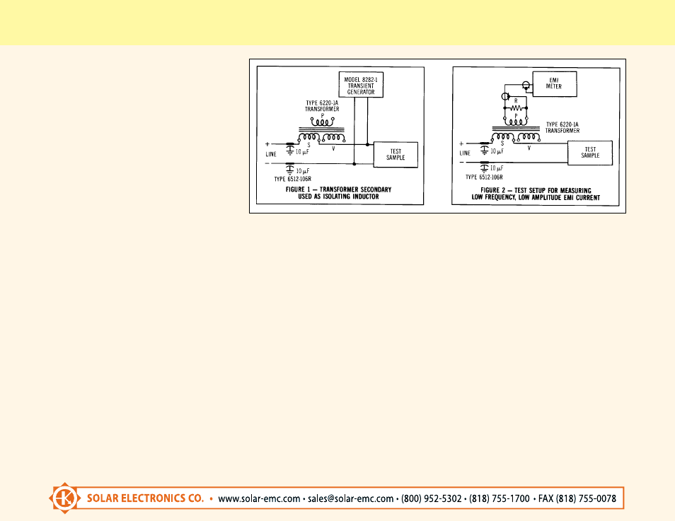
USE OF THE TYPE 6220-1A
TRANSFORMER IN GENERAL
Since the transformer is connected in series with
each ungrounded power input lead (sequentially)
for performing the audio susceptibility tests, it can
be used for two additional purposes while still in
the circuit. First, the secondary winding can act
as the series inductor suggested for transient
injection tests to prevent the transient from being
short-circuited by the impedance of the power
line. In this application all other windings are left
open. See Figure 1. Secondly, the transformer
can be used for measuring EMI current as
described herein. See Figure 2. At other times, if
it is not needed in the circuit, short cicuiting the
primary winding will effectively reduce the
secondary inductance to a value so low that the
transformer acts as if it isn’t there.
ACHIEVING MAXIMUM SENSITIVITY
FOR CONDUCTED EMI CURRENT
MEASUREMENTS
The basic circuit in Figure 2 provides the most
pickup and transfer of energy over the frequency
range 30 Hz to 150 KHz. Curve #1 of Figure 3
shows the correction factors required to convert
narrowband signals to dB above one microam-
pere. Since the sign of the factor is negative for
most of the range, the sensitivity is considerably
better than that of conventional current probes.
The sensitivity achieved by this technique is
better than .05 microamperes at frequencies
60