Electrostatic discharge immunity test, Simplified diagram of the esd generator, Esd test instruments – Atec Kikusui-KES4022A User Manual
Page 4: Distributor
Electrostatic discharge immunity test
Outline of the IEC61000-4-2 Ed 2.0
This standard stipulates the immunity requirements and test methods for electrical and
electronic equipment subjected to static electricity discharges, from operators directly,
and from personnel to adjacent objects. It additionally defines ranges of test levels
which relates to different environmental and installation conditions and establishes test
procedures.
The range of the preferred test level for the ESD testing
Level
Contact discharge
Air discharge
1
2kV
2kV
2
4kV
4kV
3
6kV
8kV
4
8kV
15kV
X
special
special
* X can be set at any level specifed by the manufacturer and the user.
ESD test instruments
Specifi cation of the ESD generator
Energy storage capacitor
150pF
Discharge resistor
330
Ω
Output voltage
Contact discharge 8kV and Air discharge 15kV
Tolerance of the output voltage display
±5%
Polarity of the output voltage
Positive and Negative
Holding time
At least 5 seconds
Discharge operation mode
Single discharge (discharge interval must be at least 1 second)
Discharge current waveform
Refer to the fi gure as shown on the right
The defi nition of the output current waveform of the ESD generator
Level
Indicated
voltage
First peak
current of
discharge
(±15%)Ip
Rise time tr with
discharge
switch(±25%)
Current (±30%)
at 30 ns
Current (±30%)
at 60 ns
1
2kV
7.5A
0.8ns
4A
2A
2
4kV
15A
0.8ns
8A
4A
3
6kV
22.5A
0.8ns
12A
6A
4
8kV
30A
0.8ns
16A
8A
●
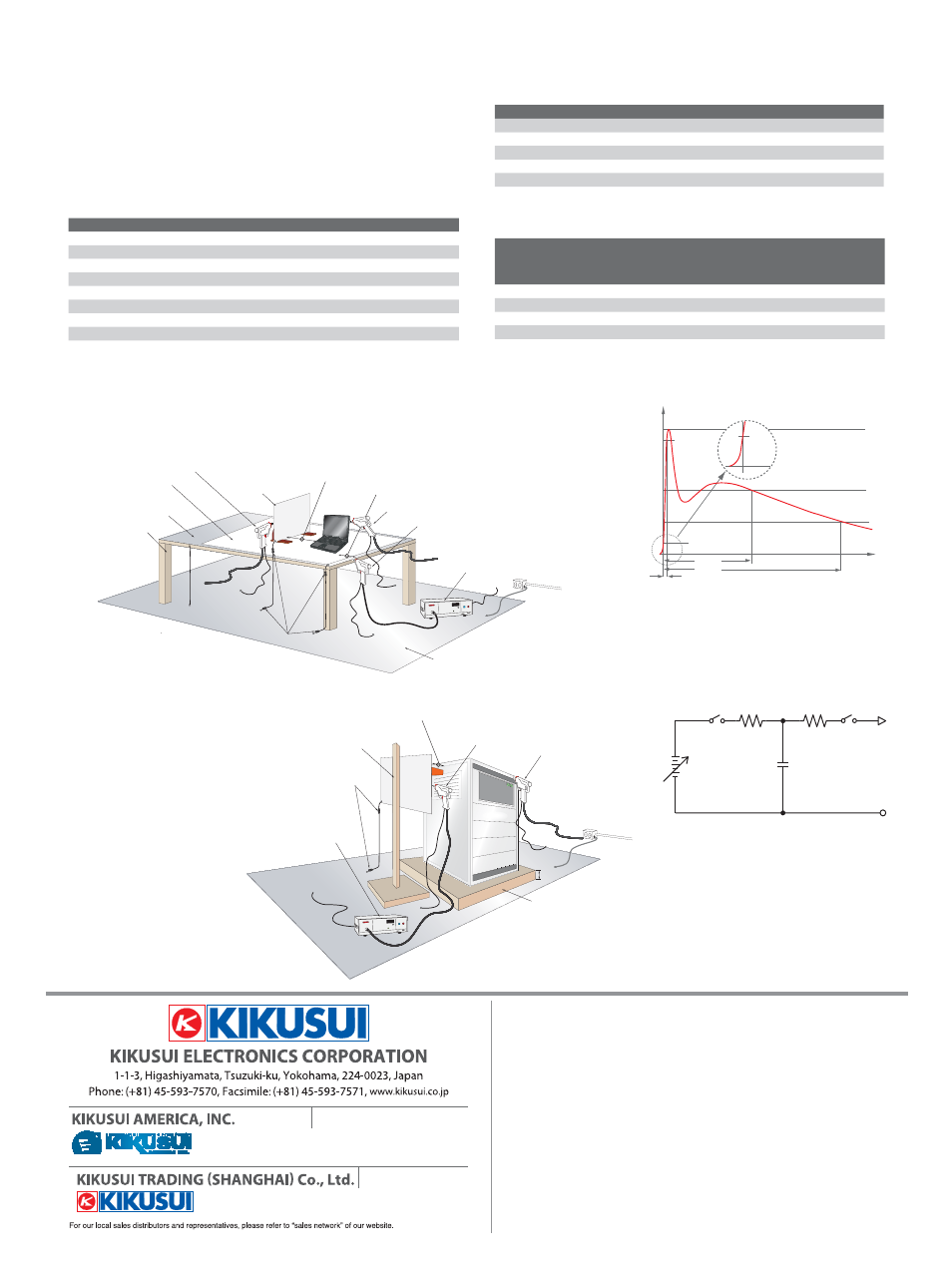
Sample layout of the test instruments for the Table-top equipment
●
Typical waveform of the discharge
output current of the ESD generator
Cs+Cd
Cs+Cd: 150pF (typical value)
Cd: Distribution volume existed between the generator and
peripheral devices
Rd
:3307 (typical value)
DC HV
Supply
●
Simplified diagram of the ESD generator
●
Sample layout of the test instruments for the Floor-standing equipment
470k
7 resistor(Resistance cable)
Vertical coupling plane
0.5m×0.5m
Ground reference plane
Test table
0.8m
Horizontal coupling
plane
1.6m×0.8m
Insulation sheet
ESD generator
To the commercial
power source
Ground wire
0.1m(Distance between the vertical coupling panel and the EUT)
0.1m(Distance between the horizontal coupling panel and the EUT)
Typical position of direct discharge
Typical position of the discharge
to the horizontal coupling panel.
Typical position of the discharge
to the vertical coupling panel.
EUT
(Equipment Under Test)
Ground reference plane
Insulation pallet
470k
7 resistor(Resistance cable)
Floor-standing vertical coupling panel
Vertical coupling plane:0.5m×0.5m
ESD generator
Typical position of the discharge
to the vertical coupling panel.
Typical position of direct discharge
0.1m(Distance between the vertical coupling panel and the EUT)
0.05m
0.15m
To the commercial
power source
Ground wire
EUT
(Equipment Under Test)
∼
•
Put a 0.8 meter high test table (made of wood) on the ground reference
plane, then place the horizontal coupling plane on the test table.
•
Connect two 470k resistors between the horizontal coupling plane and
the ground reference plane as shown in the fi gure.
•
In the testing method of indirect discharge, it observes the effect of
EUT when discharging to the vertical or horizontal coupling plane.
●
Test method
The contact discharge testing is preferred.
The air discharge testing should be applied only when the contact discharge testing can
not be performed.
•
Put a 0.1 meter high of insulation pallet on
the ground reference plate, then place the
EUT on it.
•
The Indirect discharge testing is the test
method to observe the effect to the EUT while
discharging to the vertical coupling plane.
•
Connect two 470k resistors between the
vertical coupling plane and the ground
reference plane.
•
Place the electrostatic discharge simulator
on the ground reference plane as close as
possible.
•
Use a horizontal coupling plane (1.6m×0.8m) and a vertical coupling
plane
(0.5m×0.5m)
•
Connect two 470k resistors between the vertical coupling plane and
the ground reference plane.
•
Distance between the horizontal coupling pane and the EUT
•
Place the EUT about 0.1m from the edge of the horizontal coupling plane.
•
Place the electrostatic discharge simulator on the ground reference
plane as close as possible.
100%
90%
I 30
I 60
60ns
10%
I peak
I
t(ns)
tr=0.8ns±25%
30ns
tr
I at 60ns
I at 30ns
10%
■ All products contained in this catalogue are equipment and devices that are premised on use under the
supervision of qualified personnel, and are not designed or produced for home-use or use by general
consumers.
■ Specifi cations, design and so forth are subject to change without prior notice to improve the
quality.
■ Product names and prices are subject to change and production may be discontinued when
necessary.
■ Product names, company names and brand names contained in this catalogue represent the
respective registered trade name or trade mark.
■ Colors, textures and so forth of photographs shown in this
catalogue may differ from actual products due to a limited fi delity in printing.
■ Although every effort has been
made to provide the information as accurate as possible for this catalogue, certain details have unavoidably
been omitted due to limitations in space.
■ If you fi nd any misprints or errors in this catalogue, it would be
appreciated if you would inform us.
■Please contact our distributors to confirm specifications, price,
accessories or anything that may be unclear when placing an order or concluding a purchasing agreement.
●Distributor:
1633 Bayshore Highway, Suite 331, Burlingame, CA 94010
Phone : 650-259-5900 Facsimile : 650-259-5904
www.kikusuiamerica.com
www.kikusui.cn
Room, D-01,11F, Majesty Bld, No.138, Pudong Ave, Shanghai City
Phone : 021-5887-9067 Facsimile : 021-5887-9069
1-877-876-2807
Printed in Japan
Issue:Apr.2010 201004pdf EC11