Bite, 2 and bite 2p battery impedance test equipment, Jumpering out a cell or two – Atec Megger-BITE Series User Manual
Page 2: Clean and/or retorque intercell connectors, Electrical power generation plants, Substations: utility, railroad, industrial, Ups systems, Railroad: signals and communications, substation, Aircraft power supplies, Marine, military features and benefits
BITE
®
2 and BITE 2P
Battery Impedance Test Equipment
At any time while performing a test, the operator can
review the current test results by using arrow keys and
scrolling back through the active test screen. The operator
can also print the active test using the BITE 2P transmitter
printer. If needed, the operator can retest any of the cells
and straps in the current test. Stored data can also be
downloaded via the RS-232 connector directly to a personal
computer or the BITE 2P transmitter printer.
One additional feature of the receiver is that if you are
called away while in the middle of the test, simply shut
down the instrument and it will remember where you left
off in the test.
The clamp-on current sensor is connected to the receiver
during testing and clamped around a convenient intertier
or intercell connection within the loop created by the
transmitter’s current source leads and the battery string. If
the intercell or intertier connection consists of more cables
than the diameter of the clamp-on current sensor can
encompass, the receiver has a split-strap function.
There are optional RopeCTs
TM
available for large buss work.
With the optional bar-code wand, additional information
such as location ID, user ID, ambient and pilot cell
temperatures can be recorded and stored. There is space
on the printout to enter specific gravity readings.
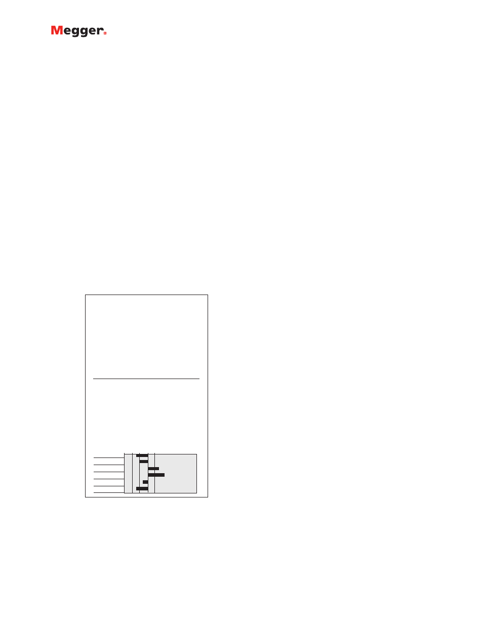
Data, measured and stored in the receiver can be exported
to a PC. It can also be printed to the BITE 2P transmitter
printer where it can be reviewed. Figure 1 shows a sample
printout of a full battery analysis report.
APPLICATIONS
A battery’s internal impedance increases with decreasing
capacity due to various conditions such as age, ambient
temperature, discharge history, etc. See Figure 2. Both the
BITE 2 and BITE 2P measure impedance values and dc
voltage for lead-acid and nickel-cadmium cells up to 7000
Ah capacity.
Impedance finds electrical path problems due to plate
sulphation, post-seal corrosion, dry-out, and poor intracell
and intercell connections. This information lets the operator
determine maintenance needs such as:
n
Cell replacement criteria based on impedance trends.
n
Jumpering out a cell or two.
n
Clean and/or retorque intercell connectors.
n
Shorten the maintenance interval, etc.
Typical installations that can be tested using the BITE 2
and BITE 2P include:
n
Electrical power generation plants.
n
Substations: utility, railroad, industrial
n
Telecommunications facilities: CO, Wireline, Wireless,
MTSO
n
UPS systems
n
Railroad: Signals and Communications, substation
n
Aircraft power supplies
n
Marine, military
FEATURES AND BENEFITS
n
On-line testing requiring no downtime.
n
Enhanced printing and memory functions.
n
Calculates impedance automatically and stores results
for on-site review.
n
Requires no battery discharge.
n
Receiver has an RS-232 connector for downloading stored
data to a personal computer.
n
Reduced test time: less than 15 seconds for each cell.
n
Measures impedance and dc voltage values for all lead-acid
and nickel-cadmium cells up to 7000 Ah.
n
Stores more than 2000 sets of readings in up to
300 tests.
n
Checks charger condition by measuring ac ripple current.
Transmitter
The transmitter provides the capacitively coupled ac test
signal to avoid transients on the dc buss and applies it to
the cells under test via the source leads. Both the BITE 2
and BITE 2P transmitters have an LCD and built-in receiver
charger, while the BITE 2P transmitter features a built-in
printer.
Battery Analysis Report
Location ID:
User ID: _ _ _ _ _ _ _ _ _ _ _ _ _ _ _ _ _ _ _ _ _ _ _ _ _ _ _ _
Notes: _ _ _ _ _ _ _ _ _ _ _ _ _ _ _ _ _ _ _ _ _ _ _ _ _ _ _ _ _
_ _ _ _ _ _ _ _ _ _ _ _ _ _ _ _ _ _ _ _ _ _ _ _ _ _ _ _ _ _ _ _ _
Ambient Temp:
Pilot Temp:
Ripple Current:
.01A
Test AC Current: 9.8 A
Multiplier: 1
B/W/F:
11.00 mW/20%/40%
05-SEP-2000
Cell
Sp.Gr.
Zb mW
P/W/F %
RS mW
Volts DC
Time
001
12.09
P 09
0.412
13.52
11:13
002
12.22
P 11
0.407
13.34
11:14
003
14.02
W 27
0.405
13.59
11:14
004
14.54
W 32
0.403
13.48
11:15
005
12.60
P 14
0.042
13.27
11:16
006
12.09
P 09
0.405
13.38
11:17
Cell Impedance Summary
Minimum
Average
Maximum
12.09
12.93
14.54
Percent Deviation from Average
-10 0
10
20
30
001
002
003
004
005
006
Figure 1. Sample battery analysis report