Fiberchekpro automated procedures – Atec JDSU-FBP-P5000 User Manual
Page 2
FIBERCHEKPRO AND P5000 DIGITAL PROBE MICROSCOPE
2
Benefits
• Eliminates human subjectivity for
consistent, standardized result when
inspecting and grading fiber
• Configurability allows for user-
defined PASS/FAIL criteria settings
• Standardizes inspection, analysis,
and grading process throughout
fiber networks
• Records and archives results in
HTML or PDF format
FiberChekPRO Automated Procedures
1. Acquires the fiber image
2. Analyzes the image
3. Finds defects and their location to fiber core
4. Measures and evaluates the defects within each specified Zone
5. Determines whether defects within the Zones are acceptable according to the
pre-configured failure criteria for each Zone
6. Displays the results as PASS or FAIL
7. Saves or prints all relative results in designated directory or printer, respectively
As different types of contamination are located and identified, FiberChekPRO
measures the size of each feature, determines its location relative to the core, and
analyzes the collected data using an advanced logarithm to obtain a PASS or FAIL
result based on the user’s desired acceptance criteria.
Because defects and contamination on or near the core surface typically affect the
light transmission most significantly, they require the most aggressive examination.
FiberChekPRO defines the concentric areas around the core as Zones which let
users establish failure criteria by evaluating various defect categories, which include
Contamination, Pit/Chip and Scratches.
Note: Zones are a series of concentric circles that identify areas of interest on the
connector end face. The inner-most zones are more sensitive to contamination than the
outer zones.
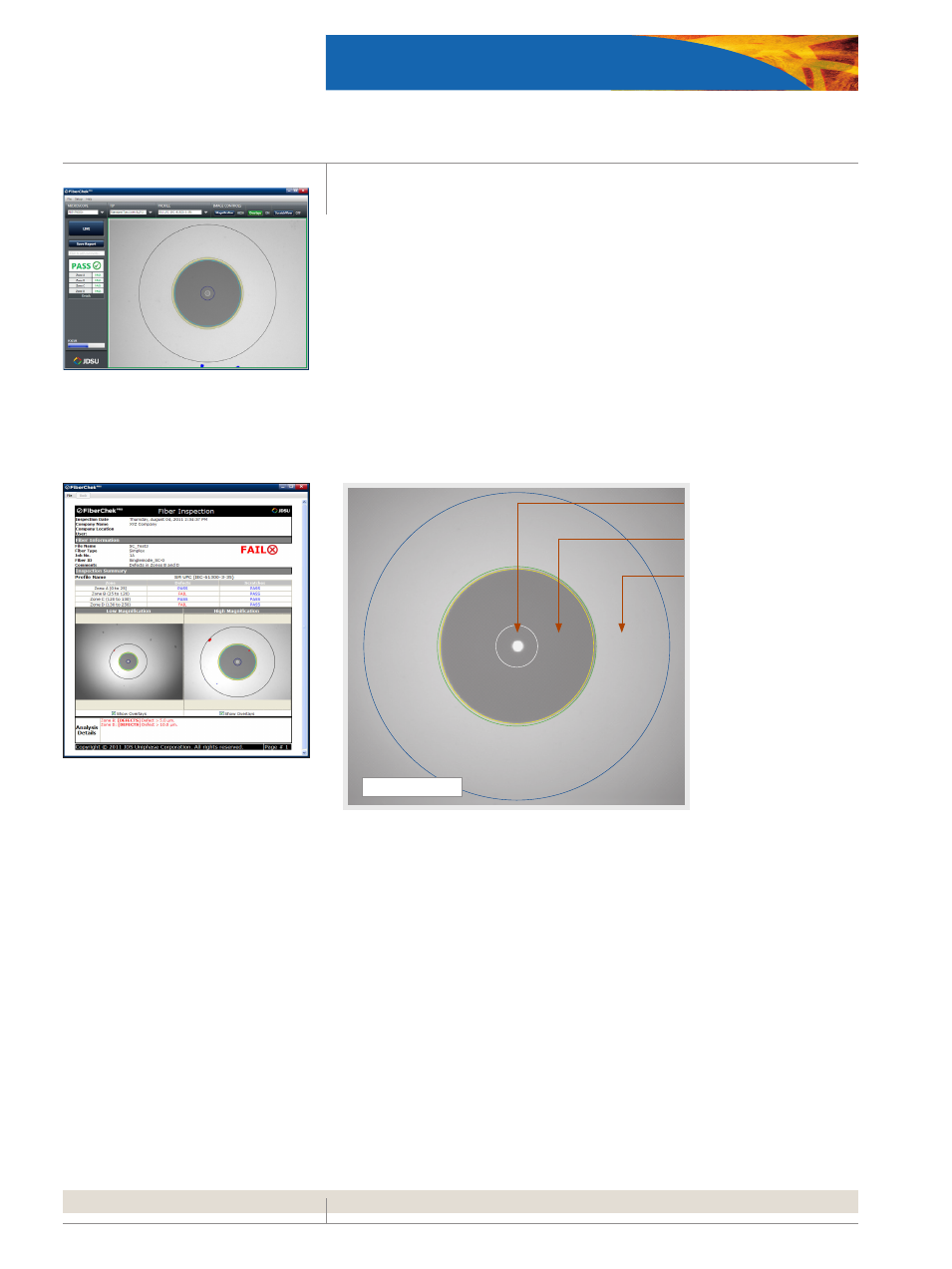
FiberChekPRO HTML Summary Report
FiberChekPRO User Interface
A
CORE Zone
B
CLADDING Zone
C
FERRULE/CONTACT Zone
SINGLE-MODE FIBER