Modular laser diode controller, Wide range of modules, Current source modules – Atec ILX-Lightwave-ldc-3900 User Manual
Page 2: Highly stable temperature control, Controller modules, Intuitive front panel, Powerful gpib interface, Specifi cations
Modular Laser
Diode Controller
LDC
3900
Modular Laser
Diode Controller
LDC
3900
Wide Range of Modules
Five current source modules and fi ve combi-
nation modules along with two TE controller only
modules make the LDC-3900 confi gurable for many
laser diode testing and control
applications. Each module is
electrically fl oating or fully iso-
lated from all other modules.
This allows you to confi gure your
laser diode test system without
the worry of potential laser diode
damaging ground loops.
Current Source
Modules
The LDC-3900 current source
design offers superior laser
protection and low noise, high
stability performance. These
modules also feature a photo-
diode measurement circuit for
devices with backfacet monitor
photodiode and analog modulation up to 500kHz
for dithering the laser current for wavelength tuning.
Five different current source modules up to 8A can
be driven in any one of the following modes:
1) Constant current, low bandwidth
2) Constant current, high bandwidth
3) Constant optical power
Highly Stable Temperature Control
The LDC-3900 TEC modules control tempera-
ture of your devices with 32W of power. These TEC
modules offer maximum fl exibility with a choice
of operating modes and temperature sensors
covering thermistors, IC, and RTDs. A low noise,
biopolar output with TE voltage measurement and
an ultra-stable topology achieves stabilities better
than 0.005°C. A smart integrator control loop, pro-
grammable from the front panel or through GPIB,
delivers fast settling times.
Controller Modules
Controller modules combine a current source
with a temperature controller in one module. Laser
current from 200mA to 2A is available with an
integrated 12W temperature controller for current
and temperature control of laser diodes. All of the
features found in the current only and temperature
control modules are incorporated into these fl exible
modules and include multiple modes of operation,
external modulation, a choice
of temperature sensors, and all
protection features.
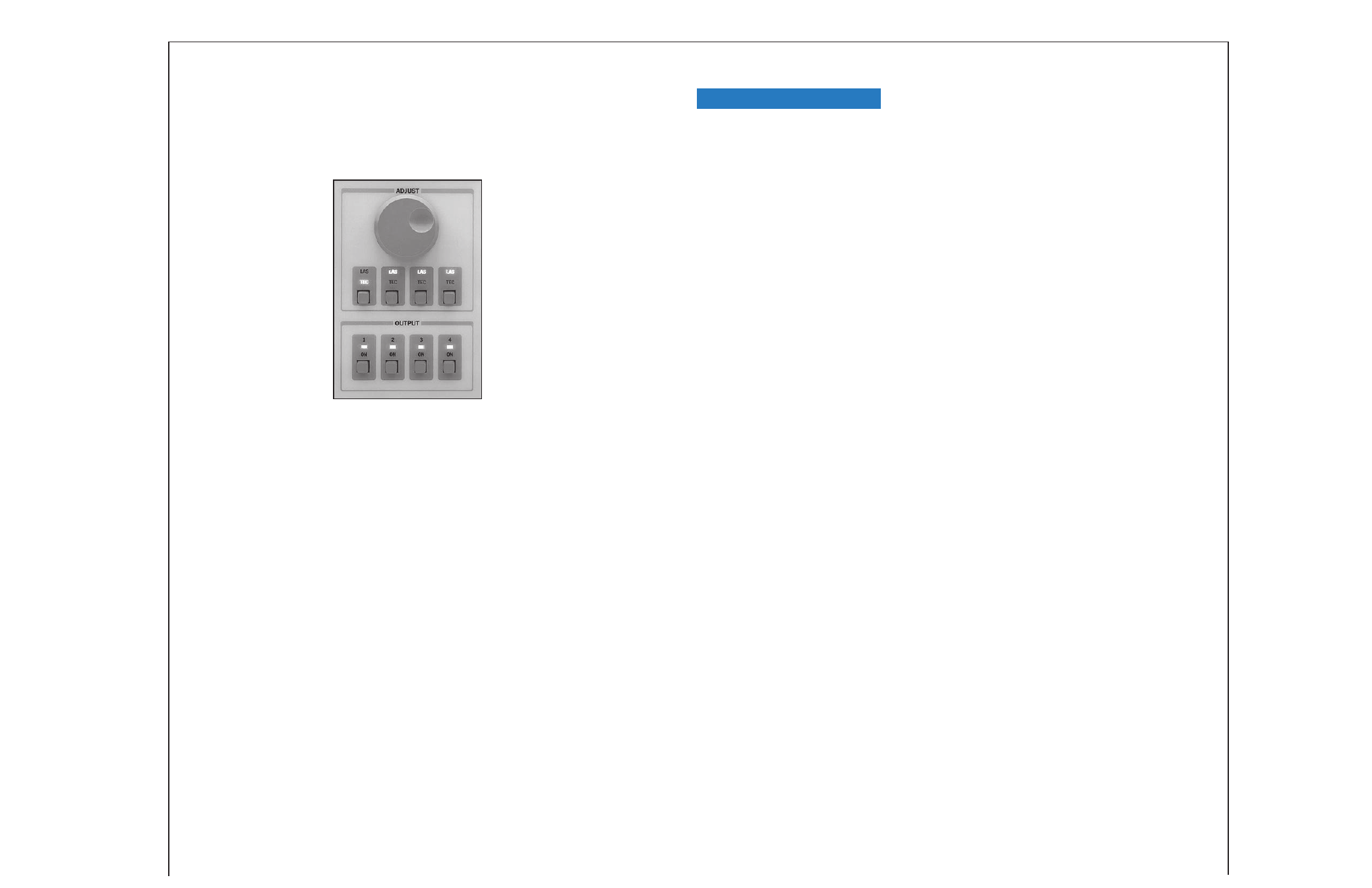
Intuitive Front Panel
Divided into two sections, TEC
and LASER, the front panel offers
quick, easy operation and infor-
mation display without confusing
multi-layer menus. Each channel is
directly addressable from the front
panel “adjust” section and indi-
cated through discrete LEDs next
to the respective display. Laser
and TEC parameters and modes
are easily selected or adjusted
through discrete pushbuttons.
Powerful GPIB Interface
For automated control, the
IEEE/GPIB interface allows programming and
readout from most computers. All instrument
and module functions are accessible through the
interface allowing you to simultaneously control
multiple laser diodes from the same address.
For virtual instrument programming, LabVIEW
®
drivers are available upon request or through the
ILX website.
* Semiconductor lasers are sensitive devices. Always
take appropriate antistatic precautions and use extreme
care when handling laser diodes. For more information,
request ILX Application Note #3, “Protecting Your Laser
Diode.”
Up to four modules can be easily
adjusted and controlled from the
LDC-3900 front panel.
Current Source Modules
1
Current Source
1
39020 39050 39100 39400
39800
14
DRIVE CURRENT OUTPUT
Output Current Range:
0–200mA
0–500mA
0–1000mA
0–4000mA
0–8000mA
Setpoint
Resolution:
10µA
10µA
100µA
100µA
125µA
Accuracy:
±0.1% of FS
±0.1% of FS
±0.1% of FS
±0.1% of FS
±0.1 % of FS
Compliance Voltage:
7V
6.5V
6V
5V
5V at connector
(4.5V end of cable)
Temperature Coeffi cient:
<60ppm/°C
<60ppm/°C
<100ppm/°C
<100ppm/°C
<100ppm/°C
Short-Term Stability (one-hour):
2
<20ppm
<20ppm
<20ppm
<20ppm
<20ppm
Long-Term Stability (24 hours):
3
<50ppm
<40ppm
<40ppm
<40ppm
<40ppm
Noise and Ripple (µA rms)
4
High Bandwidth Mode:
<3µA
<5µA
<10µA
<15µA
<120µA
Low Bandwidth Mode:
<2.5µA
<3µA
<5µA
<5µA
<110µA
With LNF-320:
5
<1µA
<1.5µA
<2.5µA
<3µA
N/A
Transients:
Operational:
6
<1mA
<1mA
<2mA
<5mA
<8mA
Power-line spike induced:
7
<5mA/<8mA
<5mA/<8mA
<5mA/<8mA
<10mA/<20mA
<20mA/<40mA
Isolation:
All modules isolated from other modules and earth ground
DRIVE CURRENT LIMIT SETTINGS
Range:
0–200mA
0–500mA
0–1000 mA
0–4000mA
0–8000mA
Resolution:
0.5mA
2mA
4mA
16mA
40mA
Accuracy:
±2mA
±5mA
±10mA
±40mA
±80mA
PHOTODIODE FEEDBACK
Type:
Transimpedance
Transimpedance
Transimpedance Transimpedance
Transimpedance
Reverse Bias:
0–5V, adjustable
0–5V, adjustable
0–5V, adjustable
0–5V, adjustable
0–5V, adjustable
Photodiode Current Range:
0–5mA
0–5mA
0–10mA
0–20mA
0–20mA
Output Stability:
8
0.02%
0.02%
0.02%
0.02%
0.02%
Setpoint Accuracy:
±0.05% of FS
±0.05% of FS
±0.05% of FS
±0.1% of FS
±0.1% of FS
EXTERNAL ANALOG MODULATION
Input: 0–10V,
10k
Ω
0–10V, 10k
Ω
0–10V, 10k
Ω
0–10V, 10k
Ω
0–10V, 10k
Ω
Transfer Function:
20mA/V
50mA/V
100mA/V
400 mA/V
800mA/V
Bandwidth (3dB)
High
Bandwidth:
9
DC to 500kHz
DC to 200kHz
DC to 200kHz
DC to 50kHz
DC to 50kHz
Low Bandwidth:
DC to 5kHz
DC to 5kHz
DC to 5kHz
DC to 2kHz
DC to 2kHz
Low Bandwidth CW:
5
DC to 30Hz
DC to 30Hz
DC to 30Hz
DC to 30Hz
DC to 30Hz
OUTPUT CONNECTORS
Current Source Output:
9-pin, D-sub
9-pin, D-sub
9-pin, D-sub
9-pin, D-sub
16-pin,
Bulkhead
Photodiode Input:
Coax BNC
Coax BNC
Coax BNC
Coax BNC
Coax BNC
Analog Modulation Input:
Coax BNC
Coax BNC
Coax BNC
Coax BNC
Coax BNC
inst. amp. input
inst. amp. input
inst. amp. input
inst. amp. input
inst. amp. input
MEASUREMENT (DISPLAY)
10
Output Current
Range:
0–200.00mA
0–500.00mA
0–1000.0mA
0–4000.0mA
0–8000.0mA
Resolution:
0.01mA
0.01mA
0.1mA
0.1mA
0.1mA
Accuracy:
11
±0.05% of FS
±0.1% of FS
±0.1% of FS
±0.1% of FS
±0.1% FS
Photodiode Current
Range:
0–5000µA
0–5000µA
0–10,000µA
0–20,000µA
0–20,000µA
Resolution:
1µA
1µA
1µA
1µA
1µA
Accuracy:
11
±2µA
±2µA
±2µA
±4µA
±4µA
Photodiode Responsivity
Range:
12
0.00–600.00µA/mW 0.00–600.00µA/mW 0.00–600.00µA/mW 0.00–600.00µA/mW
0.00–1000.00µA/mW
Resolution:
0.01µA/mW
0.01µA/mW
0.01µA/mW
0.01µA/mW
0.01µA/mW
Optical Power
Range:
0.00–200.00mW
0.00–500.00mW
0.00–1000.0mW
0.00–5000.0mW
0.00–8000.0mW
Resolution:
0.01mW
0.1mW
0.1mW
0.1mW
0.1mW
Forward Voltage
Range:
0.000–7.000V
0.000–7.000V
0.000– 7.000V
0.000–5.000V
0.000–5.000V
Resolution:
1mV
1mV
1mV
1 mV
1mV
Accuracy:
13
±3mV
±3mV
±3mV
±3mV
±5mV
CURRENT SOURCES NOTES
1 All values relate to a one-hour warm-up period.
2 Over any one-hour period, half-scale output at 25°C ambient.
3 Over any 24-hour period, half-scale output at 25°C ambient.
4 Measured optically from resulting intensity fl uctuations of a laser diode with a
150kHz bandwidth photodetector. Measurements made with 1MHz detector are
typically 10% higher.
5 With model LNF-320 low noise CW fi lter enabled.
6 Maximum output current transient resulting from normal operational situations
(i.e., power on-off, current on-off), as well as accidental situations
(i.e., power line plug removal). For more information, request ILX "Transient Test
Standards”
#LDC-00196.
7 Maximum output current transient resulting from a 1000V power line transient spike.
Tested to ILX Lightwave Technical Standard #LDC-00196.
8 Maximum monitor photodiode current drift over any 30 minute period. Assumes
zero drift in responsivity of photodiode.
9 50% modulation at mid-scale output.
10 Displayed on LDC-3900 mainframe front panel “LASER” section.
11 Measured at 25°C.
12 Responsivity value is user-defi ned and is used to calculate the optical power.
13 Voltage measurement accuracy while driving calibration load. Connected at the
rear panel connector. Accuracy may vary depending on load and cable length used.
14 Model 39800 8A module uses two rear-panel module bays.
Specifi cations