Panel overview, Top view, Front view – Atec JDSU-JD725A User Manual
Page 2: Jd725a cable and antenna analyzer
2
JD725A CABLE AND ANTENNA ANALYZER
Panel Overview
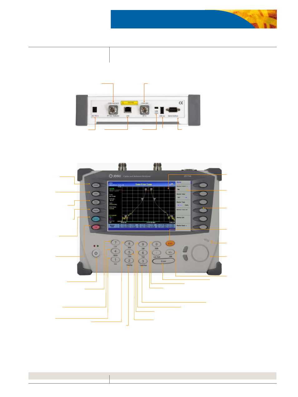
Top View
SERIAL
D-sub serial
interface port to
connect an optional
external power
sensor
USB Host
USB Memory Stick
port, used for either
saving measurement
data or upgrading the
instrument’s firmware
LAN
Ethernet
Communication Port
To connect a PC with
the application SW
RF Out/Reflection
50ohm N-type RF Connector
to measure VSWR, DTF and
One port cable loss
DC 15V IN
External DC
input port
RF In
50ohm N-type RF Connector, in conjunction with
RF Out/Reflection port, to measure amplifier
gain and cable insertion loss
USB Client
USB Port to
connect a PC with
the application SW
Front View
7 “ COLOR LCD
Daylight viewable
high resolution LCD
display
SCREEN MENU
Displays selectable
menu in connection
with function keys or
soft keys
ESC
Cancels latest
selection or moves
to previous menu
SPEAKER
Generates audio, if
enabled, for alarms and
key selections
KNOB & UP/DOWN
Moves marker positions
of items on the table list
ENTER
Finishes an
“
entry”,
which is
value or test
parameter
AUTO SCALE
Adjusts Y scale on
screen for optimal
display of traces
TRACE POINT
Selects trace points among
126, 251, 501 or 1001
TRACE
Captures up to 4 traces
Assign saved trace to Trace #
FREQ / DIST
Sets frequency range or selects a
standard or custom frequency band.
Sets distance and selects standard or
custom cables
MARKER
Supports six markers
for each trace
LOAD
Recalls saved
traces to compare
with current or other
saved traces
POWER & LED
Power ON/OFF
Green LED:
Power On status
Red LED:
External power
CAL
Performs
calibration for
VSWR, DTF,
Cable Loss and
Gain/Loss
measurements
SYSTEM
Presents system
information or
upgrades the
instrument's firmware
POWER METER and
SIGNAL GENERATOR
Measures transmission
power and generates a
CW signal
GAIN/ LOSS
Measures amplifier
gain and cable
insertion loss
VSWR
Measures impedance
matching
DTF
Measures distance
to fault location
HOLD
Pauses current
measurement display
SCALE
Changes Y-axis
scale, VSWR or
Return Loss or
Smith Chart
PEAK
Identifies the highest
peak of the trace
LIGHT
Sets LCD Brightness
AMP
Sets Y-axis Min /Max,
limit and limit level
SAVE
Saves screen,
trace, and setup
SOFT KEY
Selects menu
displayed
on the screen