Digital transmission measuring instruments – Atec Anritsu-MP1763B User Manual
Page 2
DIGITAL TRANSMISSION MEASURING INSTRUMENTS
324
•
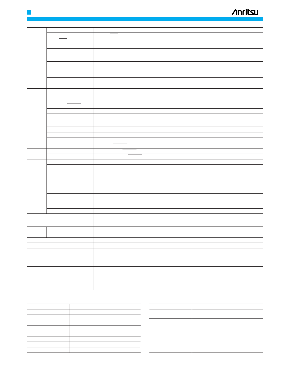
Numerical relation between data length and step width
Data length
Step width
2 to 65536
1 step
65536 to 131072
2 step
131072 to 262144
4 step
262144 to 524288
8 step
524228 to 1048576
16 step
1048576 to 2097152
32 step
2097152 to 4194304
64 step
4194304 to 8388608
128 step
Output waveform
NRZ
Number of outputs
2 (DATA/DATA)
DATA/DATA tracking mode
ON/OFF selectable
Amplitude
0.25 to 2 Vp-p, 2 mV steps (setting error: ±15% or ±100 mV, whichever is greater)
Voltage: –2 to ±2 V (V
OH
), 1 mV steps (setting error: ±15% of offset voltage, ±100 mV or ±15% of amplitude
Data
Offset voltage
whichever is the greatest
output
Display: V
OH
, V
TH
or V
OL
selectable
Rise/fall time
Typical 30 ps (10% to 90% of amplitude)
Pattern jitter
≤
20 psp-p (typical 10 psp-p)
Waveform distortion
≤
15% or
≤
150 mV whichever is greater
Load impedance
50
Ω
(with back termination)
Connector
APC-3.5
Number of outputs
3 (CLOCK 1, CLOCK 1, CLOCK 2)
CLOCK delay
±500 ps (1 ps steps)
Amplitude
0.25 to 2 Vp-p (2 mV steps)
(CLOCK 1, CLOCK 1)
Setting error: ±15% (1.5 to 2 Vp-p), ±25% (0.5 to 1.5 Vp-p), ±100 mV (0.25 to 0.5 Vp-p)
Amplitude (CLOCK 2)
1 Vp-p ±35%
Clock
Voltage: –2 to ±2 V (V
OH
), 1 mV steps (setting error: ±15% of offset voltage, ±100 mV or ±15% of amplitude
output
Offset voltage
whichever is the greatest)
(CLOCK 1, CLOCK 1)
Display: V
OH
, V
TH
or V
OL
selectable
Offset voltage (CLOCK 2)
0 V ±200 mV (V
OH
)
Rise/fall time
Typical 30 ps (10% to 90% of amplitude)
Waveform distortion
≤
15% or
≤
150 mV whichever is greater
Duty factor adjust function
CLOCK 1, CLOCK 1 adjustable
Clock
Load impedance
50
Ω
(CLOCK 1, CLOCK 1: with back termination)
output
Connector
APC-3.5 (CLOCK 1, CLOCK 1), SMA (CLOCK 2)
Number of outputs
DATA: 4, CLOCK: 1
Output level
0.5 to 2 Vp-p, 2 mV steps (setting error: ±15% or ±100 mV, whichever is greater)
Voltage: –1.5 to +1.5 V (V
OH
), 1 mV steps (setting error: ±15% of offset voltage or ±15% of amplitude or
Offset voltage
±100 mV whichever is the greatest)
1/4 data
Display: V
OH
, V
TH
or V
OL
selectable
and clock
Rise/fall time
≤
150 ps (20% to 80% of amplitude)
output*
2
Data output jitter
≤
100 psp-p
Waveform distortion
≤
15%
Skew
(DATA/DATA, DATA/CLOCK)
≤
100 ps
Connector
SMA
Number of outputs: DATA 8, CLOCK 1
1/8 data, clock output*
3
Output level: ECL
Connector: SMA
Sync. signal
Number of outputs
1 (1/32 clock, fixed position pattern, or variable position pattern selectable)
output
Output level
Amplitude: 1 Vp-p ±20%, offset voltage: 0 V ±200 mV (V
OH
)
External control
GPIB, IEEE 488.2
Operating temperature range
0˚ to +50˚C
Media: 3.5 inch FD (2HD, 2DD)
Parameter memory
Format: MS-DOS (Rev. 3.1)*
4
Content: Programmable pattern and other parameters
Power
*
5
Vac ±10%, 50/60 Hz,
≤
700 VA
Dimensions and mass
426 (W) x 221 (H) x 451 (D) mm,
≤
33 kg
EN55011: 1991, Group 1, Class A
EMC
EN50082-1: 1992
Harmonic current emissions: EN61000-3-2 (1995)
Safety
EN61010-1: 1993 (Installation Category
ΙΙ
, Pollution Degree
ΙΙ
)
*
1: Relationship between number of pages and items of word length, number of words, and data length
•
Relationship between pages of WORD mode and DATA mode
Output pattern/mode
Variable page range
WORD
1 word to the number of words that have
been set, 1 step width
1 to < data length/16, 1 step width (up to
quotient value when the remainder is 0, up to
quotient value +1, 1 step width)
DATA
Data length Number of pages
2 to 16
1
17 to 32
2
33 to 48
3
≥
49
≥
4