Agilent dc electronic loads, Ab c d g – Atec Agilent-60502B User Manual
Page 2
System or Manual Applications
Agilent dc electronic loads are equally suitable for manual use on
the bench. The front-panel LCD meters indicate voltage, current,
and power readings. The full-function front-panel keypad allows
easy, repeatable, and reliable control of the load when it is used
manually. Six volatile user-definable states allow you to easily
save settings for later recall. An additional user-definable power-
up state allows you to define settings that are remembered when
the unit is switched off and then recalled when it is switched
on again.
Specifying System Performance
Because Agilent electronic loads feature an integrated GPIB
programmer, pulse generator, current shunt, DMM, and cabling,
their performance is specified as a system. Specifications cover all
the integrated functions as one unit, which eliminates the need to
calculate the actual performance of the automated test system
based on each component’s specification. The one-box solution
makes the integration and documentation of your test system
fast and easy.
Single-Input Products
The 6060B and 6063B are single-input loads with standard rear-
panel inputs. They are also available with optional front-panel
inputs in addition to the rear-panel inputs. Front-panel inputs
(Option 020) make input connections to the electronic load
convenient for bench applications. These front-panel terminals
are capable of handling the entire current rating of the load and
can accept wire gauges up to AWG#4 (22 mm
2
). They require no
tools to tighten, making the connections quick and easy.
Mainframe Products
The 6050A 1,800-W and 6051A 600-W electronic load mainframes
accept the user-installable load modules for easy system config-
uration and future reconfiguration, if desired. The 6050A holds up
to six 60501B, 60502B, and 60503B load modules, or three 60504B
and 60507B load modules, allowing up to 1,800 W of total maxi-
mum power. The 6051A holds up to two 60501B, 60502B, 60503B
modules, or one 60504B or 60507B module allowing up to 600 W
of total maximum power. One GPIB address is all you need for
complete control and readback of all load modules within a single
mainframe.
Operating Agilent Loads Below the Minimum Input
Voltage Specification
Agilent electronic loads meet all specifications when operated
above 3.0 V; however, the dc operating characteristics also extend
below this minimum-input voltage for static tests. Because of the
FET technology used in the power input circuits, these electronic
loads have a low minimum- input resistance allowing them to sink
high currents even at low voltages.
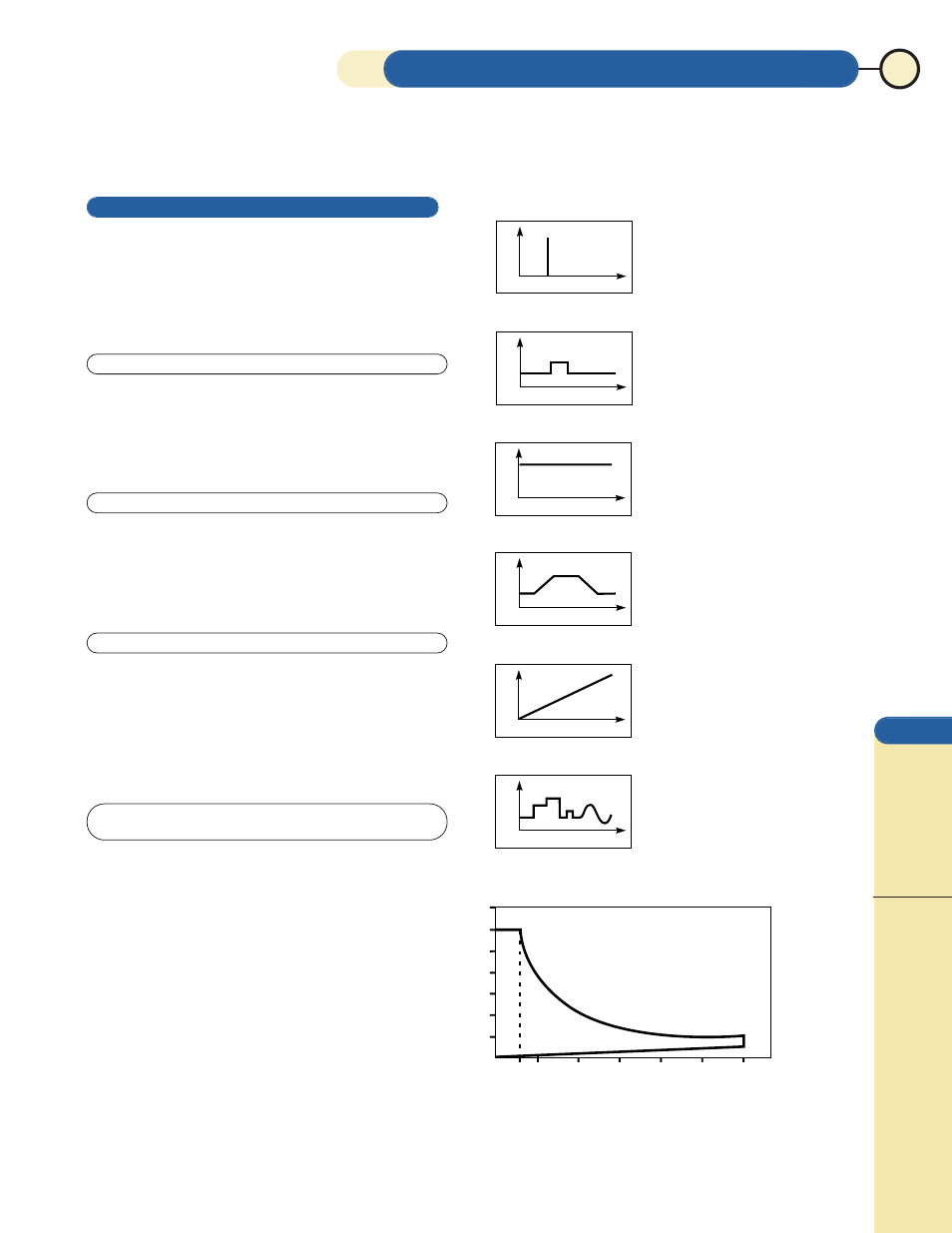
Figure A shows the operating range of a typical Agilent dc
electronic load. Notice that low-voltage operation, down to zero
volts, is possible at correspondingly-reduced current levels,
depending on the minimum resistance of the load. These electronic
loads, therefore, can be used in many applications that previously
required zero-volt loads.
AGILENT dc ELECTRONIC LOADS
39
0
0
0
0
0
0
0
300 Watts
5
10
20
30
40
50
60
Amperes
300 Watts
V
olts
10
20
30
40
50
60
70
Figure A
V
I
V
I
V
I
V
T
V
T
V
T
Characterizing
Power Supply Crossover
Power Supply
Start-Up Delay
Power Resistor Emulation
Power Supply Load
Regulation Testing
Battery Capacity
Testing
Capacitor Discharging
Power Supply Load
Transient Response
Power Component
Testing
Pulse Electroplating
Battery Capacity Testing
“Real-life” Load Simulation
Constant Current
Pulse and Dynamic Loading
Constant Voltage
Constant Resistance
Programmable Slew Rate
Analog Programming
Power Supply Testing
Power Component
Testing
Power Supply Load
Transient Response
Current Source Testing
Current Limit Testing
Shunt Regulator
A
B
C
D
G
dc
Electronic
Loads
For more information in the U.S.A. call
1-800
-4
52
-4844
Recycled Equipment (410)685-1997 www.recycledequipment.com email: [email protected]