About pim – Atec Boonton-PIM31 User Manual
Page 4
PIM (Passive Intermodulation distortion)
Ideally all passive components in an RF path offer linear fre-
quency response. As with VSWR, real world conditions are not
ideal. All passive components show some degree of non-lineari-
ty. The goal is to keep it as low as possible.
The strongest intermodulation product is usually the third order
product IM3, closest to the source signals. It is calculated as
follows:
1) IM3 = 2x f1 – f2
2) IM3 = 2x f2 – f1
Where f1 is the first signal frequency and f2 is the second
signal frequency. IM3 in equations 1) and 2) are of equal power.
Using just two frequencies is a simplification since virtually
all current communication technologies utilize multitudes of
frequencies to carry the information, and therefore provide an
ideal precondition for intermodulation effects that generate
harmonics. Intermodulation products are often found within the
RX band, degrading receiver performance, or disabling receiving
channels completely. Unwanted signals present in the active
channel will desensitize the cell phone and may drop the call.
What causes PIM effects?
Dissimilar metals with different electrical potential constitute a
potential voltaic element. Humidity between them will trans-
form it to a galvanic element acting like a diode.
Ferromagnetic metals, like iron, nickel and steel, show hyster-
esis effects when energy is applied. The resulting signal level
is altered depending on input level and the actual slope of the
waves -the resulting signal response is no longer linear.
Irregular contact areas, even on a microscopic scale, cause an
inconsistent flow of charge carriers and generate inhomoge-
neous electromagnetic fields. Dissimilar expansion coefficients
of tower and feed lines can expose system connectors to sig-
nificant mechanical forces. Dissimilar expansion coefficients of
tower and feed lines can expose system connectors to signifi-
cant mechanical forces, which often results in shifted contacts
or worse, damaged contact areas.
Spark discharges caused by accidental “hot” connection / dis-
connection of components result in a combination of negative
effects: Craters in the surface, and chemical transformation of
contact plating and alloys.
About PIM
Intermodulation can occur whenever more than one signal
is present in an RF system. This is clearly the case in modern
wireless communication technologies, such as EvDo, WCDMA
/ UMTS, TD-SCDMA, WiMax or LTE. All of them use spread
spectrum signals utilizing a multitude of frequencies simultane-
ously. With a non-linear component in the RF path these signals
will mix and create spurious products.
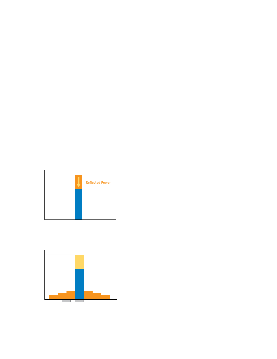
PIM vs. VSWR
Impedance match between components and systems is an im-
portant factor for transmitting RF energy. VSWR measurements
are used to determine the impedance matching conditions. Ide-
ally impedance of connected components is equal and indepen-
dent of power and frequency. In reality system impedances vary
depending on actual frequency and power levels. Impedance
mismatch causes intended transmission energy to be reflected
back to the transmitter.
Frequency
100%
Effective
Transmitted Power
PA
Output Power
Impedance Mismatch
IM3
IM5
IM5
IM7
IM7
Frequency
Rx Band
Tx Band
100%
Diverted Power
Effective
Transmitted Power
PA
Output Power
Spread Spectrum Intermodulation Effects
IM3