Atec Boonton-PIM31 User Manual
Page 3
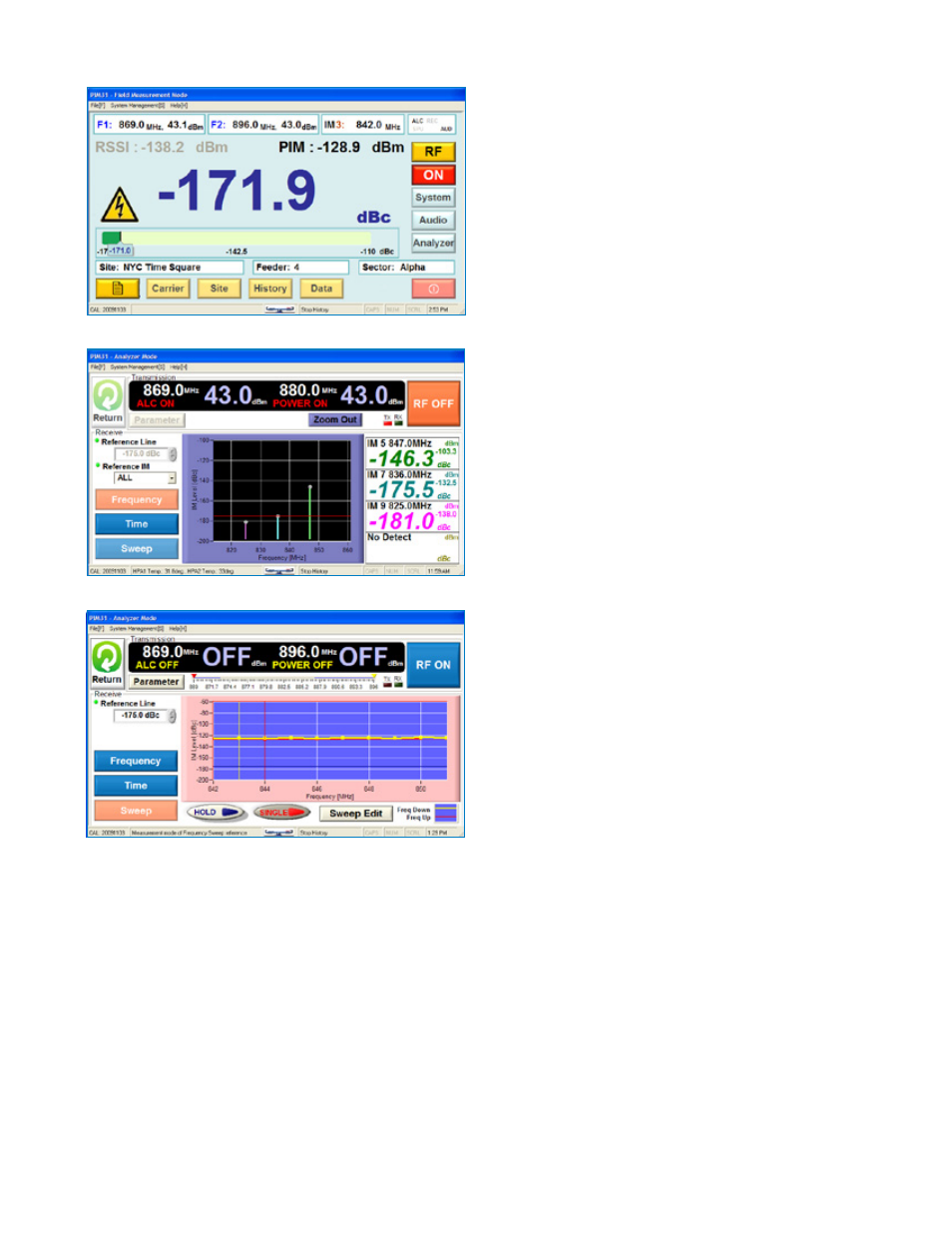
Field Diagnostic Interface*
For field applications PIM 31’s field diagnostic mode presents the
relevant information in a clear way. In this mode frequency and
power levels of the carrier signals are set. The screen shows the
PIM measurement in large digits, for easy readability even from
a greater distance. The dBm value is presented simultaneously
to the dBc value. A future software update will provide a bar
graph for immediate visual display of the measured value and its
tendencies.
Analyzer Mode
The analysis mode of the user interface provides access to all
settings. Power and frequency of each transmitted signal can
be set individually. The user interface allows the display of up to
four IM products. Reference lines for automatic Pass/Fail deci-
sions can be set. The mode of the test (PIM vs. Frequency, PIM
vs. Time, and PIM vs. PIM vs. Frequency also known as Sweep)
can be selected as well.
Sweep Mode
Sweep mode allows the user to automatically vary the frequen-
cies of the measurement band. Any up and down sweep fre-
quency range can be set within the unit bandwidth. Sweeps are
performed in 1 MHz increments. To allow for the fastest sweep
cycles, automatic level control is disabled in this mode.
Benefits to operators of RF transmission systems
• Higher customer satisfaction through higher QoS
• Reduction of maintenance costs achieved through quick
detection of components that cause PIM distortion
• Reduction of operational cost through increased network
efficiency
• Reduced capital investment through practical network
optimization
• Maximization of revenue, due to optimal use of available
bandwidth and air time.
Benefits to manufacturers of Passive RF Components
• Reduced capital investment through outstanding price /
performance ratio
• Reduction of service calls, since components can be tested
and verified on site with the same PIM analyzer used in
production
*Not available for UL models.