System overview, 2 indicators & connections, continued, Figure 1-8; data i/o connector – Alpha Technologies Serial System Controller User Manual
Page 18: Table 1-1; digital inputs and outputs
18
018-332-C0-002 Rev. B
1. System Overview
© 2001
TM
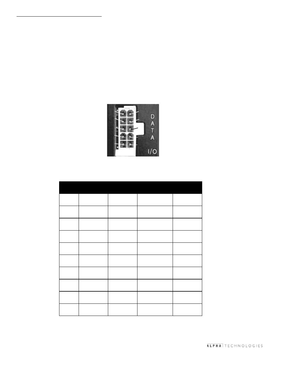
Figure 1-8; Data I/O Connector
1.2.7 Data I/O Port
The Data I/O port consists of a 10-pin user-definable set of contact closures. It
contains one discrete input, and four discrete outputs, both read by the external
communication ports. The output signals are contact closure to its return pin on
activation. The input signal is activated by a short between pins 6 and 7.
The location and function of each pin is illustrated in the figures below.
1.2 Indicators & Connections, continued
#
n
i
P
/
t
u
p
n
I
t
u
p
t
u
O
d
r
a
d
n
a
t
S
e
s
U
r
e
d
n
o
p
s
n
a
r
T
e
s
U
)
1
e
t
o
n
(
e
v
i
t
c
A
e
t
a
t
S
1
t
u
p
t
u
O
4
#
t
u
p
t
u
O
r
e
t
r
e
v
n
I
m
e
t
s
y
S
s
u
t
a
t
s
t
c
a
t
n
o
C
e
r
u
s
o
l
C
2
t
u
p
t
u
O
4
#
t
u
p
t
u
O
n
r
u
t
e
r
s
u
t
a
t
s
r
e
t
r
e
v
n
I
n
r
u
t
e
r
3
t
u
p
t
u
O
3
#
t
u
p
t
u
O
s
u
t
a
t
s
e
n
i
l
C
A
t
c
a
t
n
o
C
e
r
u
s
o
l
c
4
t
u
p
t
u
O
3
#
t
u
p
t
u
O
n
r
u
t
e
r
s
u
t
a
t
s
e
n
i
l
C
A
n
r
u
t
e
r
5
t
u
p
t
u
O
2
#
t
u
p
t
u
O
m
r
a
l
a
r
o
n
i
M
)
2
e
t
o
n
(
t
c
a
t
n
o
C
e
r
u
s
o
l
c
6
t
u
p
n
I
1
#
t
u
p
n
I
t
s
e
t
m
e
t
s
y
S
)
3
e
t
o
n
(
n
i
p
o
t
e
s
o
l
C
7
7
d
n
u
o
r
G
1
#
t
u
p
n
I
n
r
u
t
e
r
t
s
e
t
m
e
t
s
y
S
n
r
u
t
e
r
8
t
u
p
t
u
O
1
#
t
u
p
t
u
O
m
r
a
l
a
r
o
j
a
M
)
4
e
t
o
n
(
t
c
a
t
n
o
C
e
r
u
s
o
l
c
9
t
u
p
t
u
O
1
#
t
u
p
t
u
O
n
r
u
t
e
r
m
r
a
l
a
r
o
j
a
M
n
r
u
t
e
r
0
1
t
u
p
t
u
O
2
#
t
u
p
t
u
O
n
r
u
t
e
r
m
r
a
l
a
r
o
n
i
M
n
r
u
t
e
r
5
9
8
7
6
4
3
2
1
10
Table 1-1; Digital Inputs and Outputs