2 digital inputs for controller, Connection method, Programming the digital input – Alpha Technologies CXPS 48-1.2-225 48 Vdc User Manual
Page 32: Figure 13–showing digital input connection method
053-691-B1 Rev E
Page 24 of 33
5.10.2 Digital inputs for controller
The factory-installed digital input channels are used to monitor various alarm and control signals. All input
channels are voltage activated and directly accept a bipolar (negative or positive) DC signal.
D1 and D2 are available for customer connections.
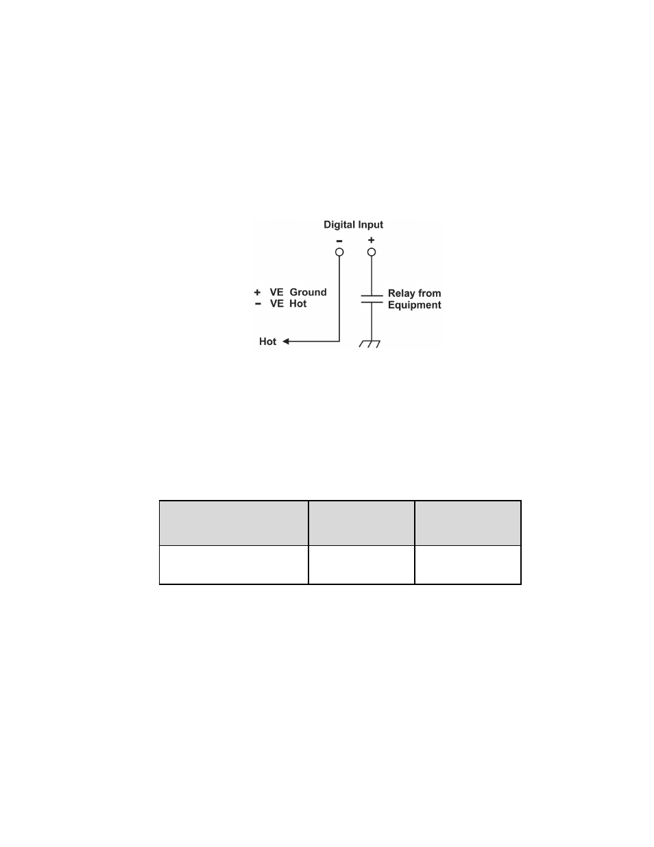
Connection method
Typical Alpha systems use a “reset with Hot and trigger with Ground” connection. The digital input is wired so
that Hot is wired directly into one of the input terminals; e.g., negative input for -48 V systems. The other
input terminal is wired to the common ground of the system through a relay, which is a dry contact usually
located on the equipment that requires monitoring. This method allows the digital input to receive or not
receive a Ground signal during an alarm. See Figure 13.
Figure 13–Showing digital input connection method
Programming the digital input
The digital input channels can be programmed for “active high” or “active low.” Active high indicates an alarm
when a ground signal is present. Active low indicates an alarm when the ground signal is removed. See the
controller software manual.
Voltage range (VDC)
Voltage level (VDC)
considered 0 or off
Voltage level (VDC)
considered 1 or on
0—60
(system voltage setting)
0—3
18—60
Table C–Voltage level definitions for digital inputs