7 alarm connections, 8 can serial ports, 1 can termination – Alpha Technologies CXPS 48-1.2-225 48 Vdc User Manual
Page 30: Alarm connections, Can serial ports, Figure 11–dcp03 wire routing example
053-691-B1 Rev E
Page 22 of 33
5.7 Alarm connections
Frequent reference is made to drawings located at the rear of this manual. Custom configurations are detailed
within the Alpha power system documentation package.
For terminal block connections, the recommended wire sizes are 0.14 - 1.50 mm
2
(#26 to #16 AWG) for a
temperature range of 0 - 50ºC (UL/CSA).
CAUTION: to reduce risk of fire, use only 0.14 mm
2
(#26 AWG) or larger wire.
Route the cables via wire-ways and use existing cable clamps to secure the existing (factory) wire harness and
the customer run signal wires. Route the signal wires along hinge points of the front door so that opening and
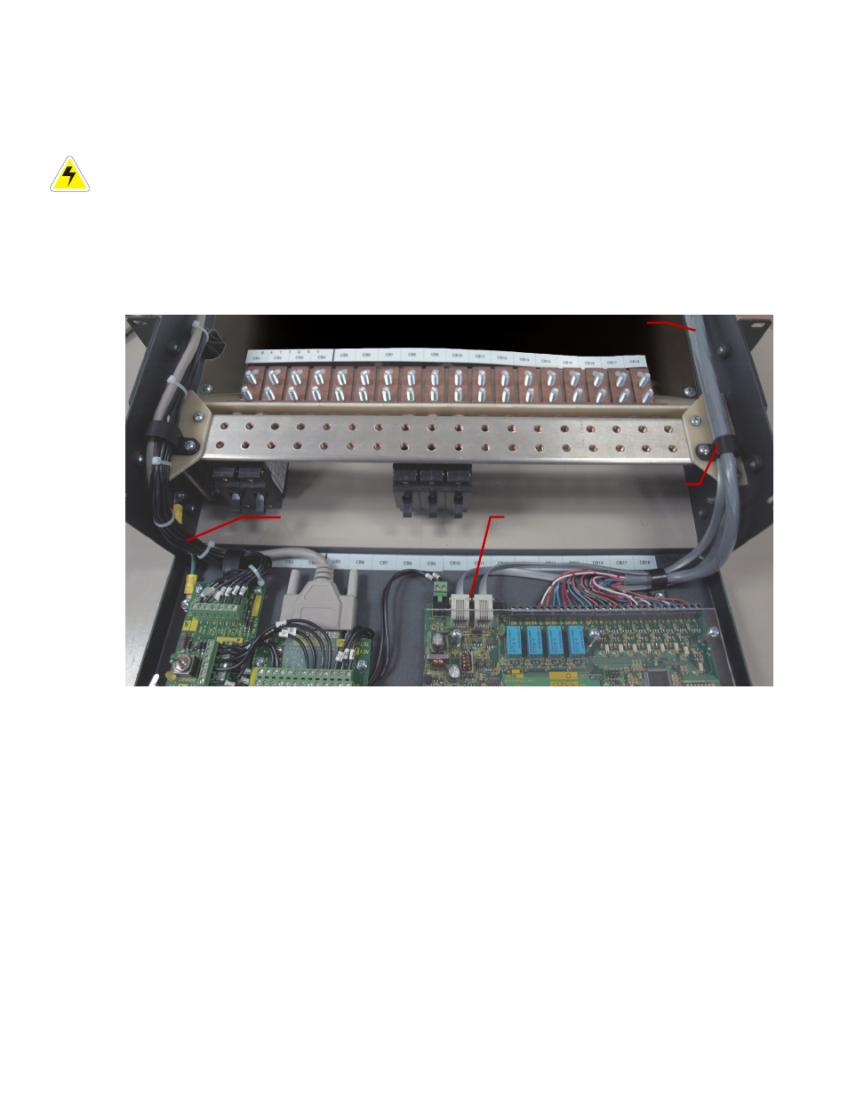
closing the door will not require excess wire slack. Refer to Figure 11 for a wire routing example.
Route the terminal block connections for the internal alarm card or controller I/O along the left side of the
distribution center (front view). Route the connections to the 4R/8D along the right hand side of the distribution
center. Refer to the customer connections (“–08”) drawing at the rear of this manual for details.
Figure 11–DCP03 wire routing example
(Photo is for reference only – subject to installation requirements)
5.8 CAN serial ports
Two CAN serial ports are located on the side of the rectifier shelf. CAN serial ports are modular jacks with offset
latches that are used to communicate with the rectifiers and other CAN-enabled equipment (nodes) on the same
system. CAN serial ports are also found on the optional 4R/8D ADIO peripheral (Figure 11).
Daisy-chain the CAN serial ports from one node to the next (CAN OUT of one shelf to CAN IN of the next).
Ensure that only the last shelf is terminated as follows:
4-module shelf – termination IN – default
5-module shelf – termination OUT – default
This system has a limit of twelve 1.2 kW rectifiers. They do not have self-powered CAN bus nodes.
5.8.1 CAN termination
A CAN termination jumper is located beside the rightmost rectifier connector on the front of the shelf backplane.
See the customer connection drawing that describes your shelf.
Cable clamp
System internal and
controller wire
4R/8D ADIO wire routing
4R/8D ADIO CAN ports