3 controller modem port (alpha cable), 10 signal wiring connections for controller, 1 alarm (relay) outputs – Alpha Technologies CXPS 48-1.2-225 48 Vdc User Manual
Page 31: Figure 12–showing relay connections
053-691-B1 Rev E
Page 23 of 33
5.9 Network connection and remote communications via controller
The Cordex system can be set up, monitored and tested via an Ethernet 10/100 Base-T serial data connection.
The communication protocol supports a web interface. Pin-outs are shown in the customer connections drawing.
Some standard scenarios are described below:
5.9.1 Ethernet port for network connection (standard network cable)
The Ethernet port is designed to connect the controller to a user supplied network (TCP/IP supplied by the user)
via a front panel RJ-45 jack. Use a standard network cable for this connection.
5.9.2 Ethernet port for local connection (crossover cable)
The Ethernet port can be used for local access to for example a laptop computer. Use a standard network
crossover cable for this connection.
5.9.3 Controller modem port (Alpha cable)
The modem port on the front panel DB-9 connector (Figure 6) is designed for a controller connection to the Alpha
Technologies Cordex DC Modem #018-585-20. Use the Alpha-supplied cable for this connection.
CAUTION: Use only an Alpha-supplied modem and cable. Otherwise the equipment may be damaged.
5.10 Signal wiring connections for controller
Reference is made to drawings located at the rear of this manual. Custom configurations may be detailed within
the Alpha power system documentation package.
For terminal block connections, the recommended wire sizes are #16 - #26 AWG (1.5 - 0.129 mm
P
2
P
) for the
temperature range of 0 - 50ºC (as per UL/CSA).
CAUTION: To reduce risk of fire, use only #26 AWG (0.129 mm
P
2
P
) or larger wire.
Bundle the signal cables together and route them through the entry holes of the shelf.
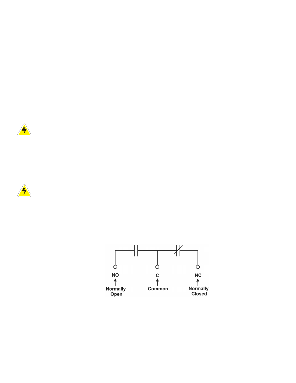
5.10.1 Alarm (relay) outputs
Terminals provide contacts for extending various alarm or control signals. Each relay output can be wired for NO
or NC operation during an alarm or control condition. See Figure 12.
Figure 12–Showing relay connections
Relays can be programmed to energize or de-energize during an alarm condition. See the controller software
manual. All relays will de-energize when the controller reset button is pressed or when the power is lost.