5 maintenance and troubleshooting, 1 preventative maintenance, 2 troubleshooting guide – Alpha Technologies INVERTER 2000 User Manual
Page 20: Aintenance and, Roubleshooting, Preventative maintenance, Troubleshooting guide, 5maintenance and troubleshooting
Alpha Technologies Ltd.
014-129-B2 Rev C WC
© 2010 Alpha
Technologies Ltd. ALPHA is a registered trademark of Alpha Technologies Ltd. All Rights Reserved.
Page 14 of 19
5
Maintenance and Troubleshooting
5.1 Preventative Maintenance
The following preventive maintenance routines should be considered as a minimum requirement. Your installation
may require additional preventive maintenance to assure optimal performance from your installed inverter and
associated equipment. These routines should be performed twice a year (more often if required). We strongly
recommend a contract with Customer Support Services for preventive and remedial maintenance. The technician
or electrician performing preventive maintenance on the equipment must read and understand thoroughly this
manual and be familiar with the indicators, controls, and operation of the equipment.
5.2 Troubleshooting Guide
If the inverter fails to operate properly after having the installation and setup of the inverter thoroughly re-
examined, use the troubleshooting table to determine the probable cause(s) and solution(s) to resolve error
conditions. For unlisted error conditions, please contact your local dealer for technical assistance.
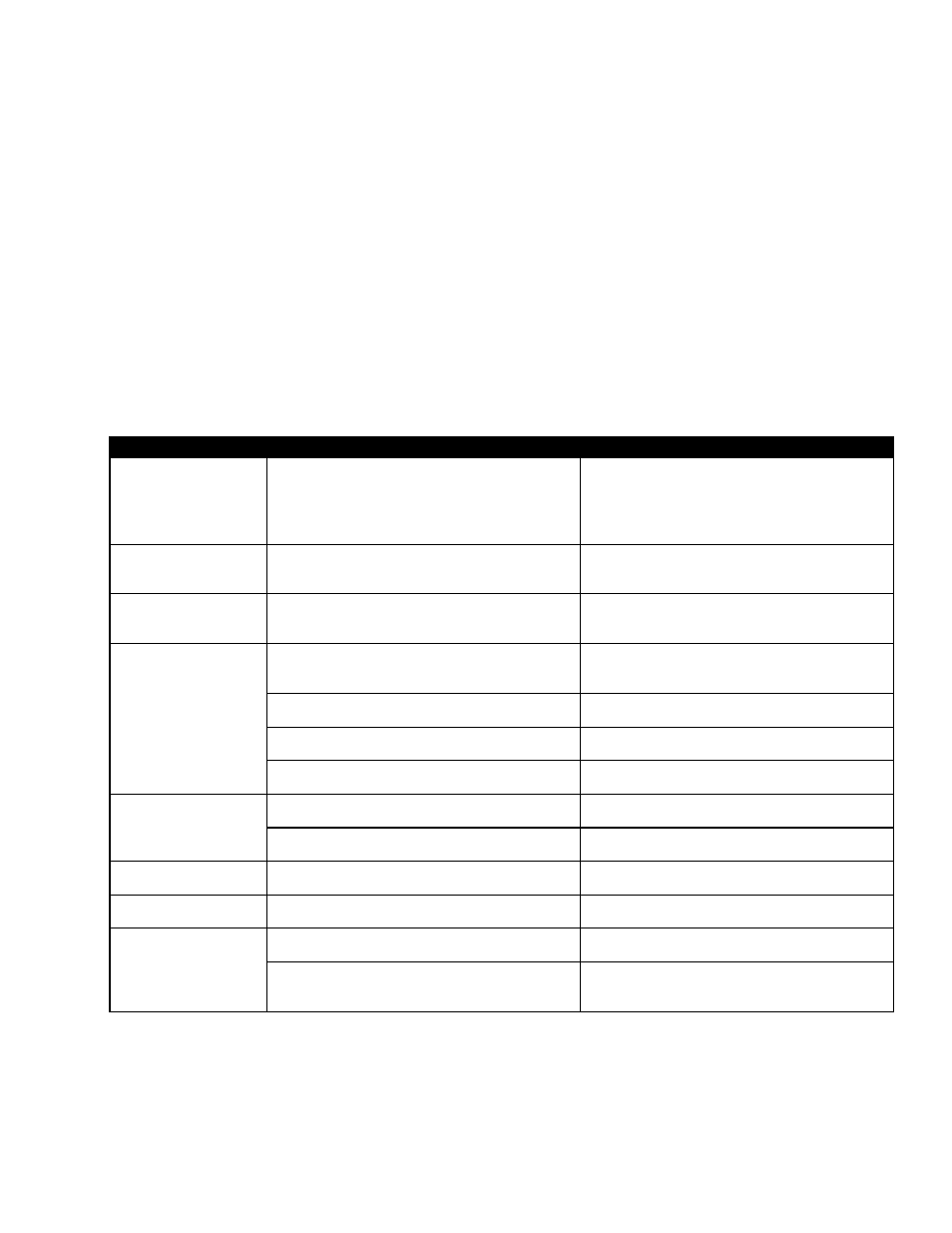
Error Condition
Possible Cause
Recommendation
No AC output
and all LEDs off.
Lack of input power.
Ensure input cables are all firmly connected to
power source.
Check if power source is not yet switched on, or
is low in power.
No AC output.
Both green and yellow
LEDs flicker.
Inverter self-diagnosis.
Inverter self-diagnosis takes a few seconds.
LED turns to a solid green light after the
completion of self-diagnosis.
No AC output.
Both yellow and red
LEDs are on.
Load exceeds 125%.
Ensure the load is no higher than 105% of the
total power rating. Reduce as required.
No AC output.
Red LED is on.
1. Input wiring is connected in reverse (i.e.
reverse polarity).
Ensure input cables are connected to correct
polarity (positive to positive, negative to
negative).
2. Internal fault.
Restart the unit. If it fails to work, return it to
factory for repair.
3. Inverter output is shorted.
Turn off the input power source to remove all
short circuits.
4. Negative Power Protection.
When transfer between Mains and inverter, mains
backfeed to inverter.
Red LED blinks fast.
1. Inverter fails to soft start.
Reboot the inverter system by switching off and
on the input power source.
2. Inverter temperature rises beyond the
temperature limit.
Leave inverter idle to cool down for few minutes.
AC output exists with
yellow LED flickering.
Input voltage is out of operating range.
Ensure input voltage is between 45 to 58Vdc.
AC output exists and
yellow LED is on.
Load is over 100% but below 125%.
Ensure the load is no higher than 105% of the
total power rating. Reduce as required.
Inverter continuously
delivers power, but with
red LED flickering
slowly.
Failure of EEPROM.
Reboot the inverter system by switching off and
on the input power source.
Fans failure.
Check if the fans are locked or fail to work.
If fan is locked, remove the obstruction;
if fan fails to work, replace the fan.
Table G–Troubleshooting for inverter module