3 led indicators, 1 power on, 2 overload and overload fault – Alpha Technologies INVERTER 2000 User Manual
Page 12: 3 priority
Alpha Technologies Ltd.
014-129-B2 Rev C WC
© 2010 Alpha
Technologies Ltd. ALPHA is a registered trademark of Alpha Technologies Ltd. All Rights Reserved.
Page 6 of 19
Figure 4–USB connectivity
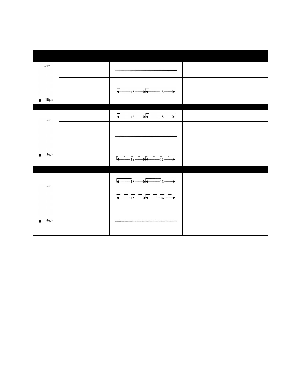
4.1.3 LED Indicators
Inverter Module LED Display Status
Priority
Green LED
LED Signal
Status
Solid
Inverter work normally
Blink (intermittent (slow))
One of the status as follows:
1) Power On.
Details refer to note.
2) Shut down remotely.
Priority
Yellow LED
LED Signal
Status
Blink (intermittent (slow))
Power On
Details refer to note.
Solid
One of the alarms as follows:
1) Over Load (Load > 105%);
2) DC input abnormal.
(Vin<=45V or Vin>=58V)
Blink (intermittent (fast))
Inverter shut down due to DC super
low/super high input.
(Vin<=VLVSD or Vin>=VHVSD)
Priority
Red LED
LED Signal
Status
Blink (slow)
One of the alarms as follows:
1) EEPROM Fault;
2) Inverter Fan Fault.
Blink (fast)
One of the alarms as follows:
1) Internal fault;
2) Temperature High.
Solid
One of the alarms as follows:
1) Input reverse polarity;
2) Inverter output Short circuit;
3) Abnormal output voltage;
4) Negative Power Protection;
5) Overload fault.
Table A–Inverter LED indicator display
4.1.3.1 Power On:
When the inverter is in “Power On” mode, the green LED and the yellow LED are flickering
synchronously without any alarm.
4.1.3.2 Overload and Overload Fault:
When overload fault alarm occurs, the yellow LED and red LED turn on at the same time, while
overload alarm occurs, only the yellow LED turns on.
4.1.3.3 Priority:
If more than one warning exists at the same time, then the LED will display the highest priority.