12 parameter dump command (function 0) – Alpha Technologies CFR 1500, CFR 1500RM User Manual
Page 64
15
2.6
RS-232 Communication Options
2. FEATURES
RS–232 Connector
The connection/specifications for the RS–232 serial port vary depending
on the installed interface device (
i.e., SID or IID option).
Rear Panel RS–232 Port
The RS–232 port on the CFR follows the Data Communication Equipment
(DCE) pinout. To connect this port to a terminal or a host computer (which uses a
DTE pinout) you need a standard off-the-shelf ("straight-through") RS–232 cable.
Depending on your computer, you need a “
9 to 9 serial cable” or a “9 to 25 serial
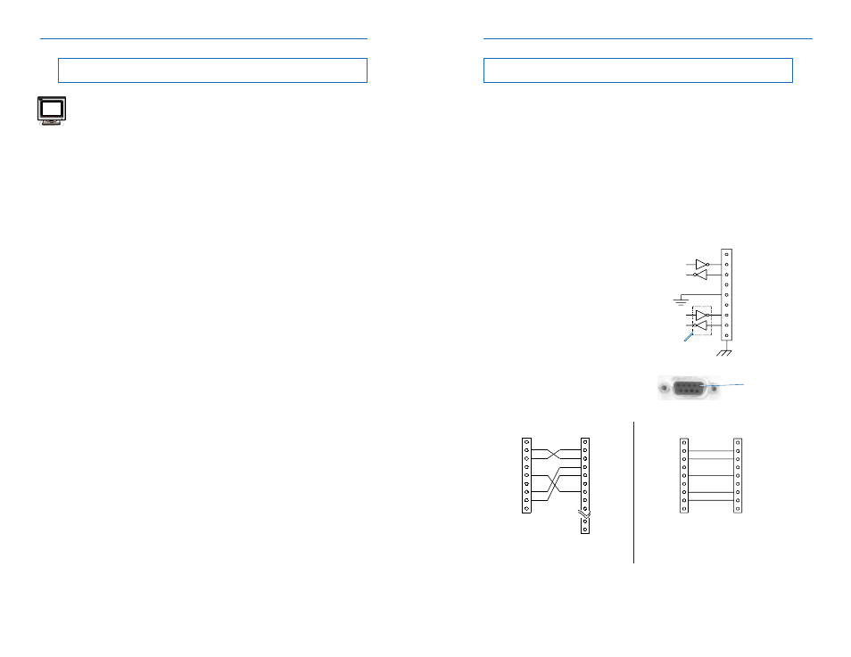
cable”. However, if you decide to make you own cable, see Fig. 9. The cable
shown works with both SID and IID. If your CFR has a SID interface, then you do
not have to wire up the RTS and CTS signals. For SID equipped units, the DE9-
DB25 cable can also be used with an external modem.
1
2 - TxD
3 - RxD
4
5 - GND
6
7 - CTS
8 - RTS
9
1
2 - TxD
3 - RxD
4 - RTS
5 - CTS
6
7 - GND
8
9
24
25
1
2 - TxD
3 - RxD
4
5 - GND
6
7 - CTS
8 - RTS
9
1
2 - RxD
3 - TxD
4
5 - GND
6
7 - RTS
8 - CTS
9
To IBM-PC
Serial Port
To CFR RS–232
Port
DE-9 Male
To CFR RS–232
Port
To IBM-PC Serial
Port or external
modem
DE-9 Male to DE-9 Female
DE-9 Male to DB-25 Female
Fig. 9 RS–232 Connector Cable Wiring
(IID to computer or terminal, SID to computer, terminal or modem)
DB-25 Female
(DTE)
DE-9 Male
DE-9 Female (DTE)
1
2 Tx
3 Rx
4
5 Gnd
6
7 RTS *
8 CTS *
9
* IID Only
Not used with SID
Communication Settings
with SID:
Baud Rate:
1200
Parity:
None
Stop Bits:
One
Data Bits:
8
Handshaking: XON / XOFF
Communication Settings
with IID:
Baud Rate:
300 to 9600
Parity:
None, Even, or Odd
Stop Bits:
1 or 2
Data Bits:
7 or 8
Handshaking: RTS/CTS
Internal CFR connections
Pin 1
58
5. RS-232 TERMINAL COMMUNICATION
5.12 Parameter Dump Command (Function 0)
Parameter Dump Command (Function 0)
Function ‘0’ displays all UPS parameters in the following format:
#####,###.#,#####,#####,##.##,###.#,#####,###.#,#####,###.#,#####,#####,##.##,
###.#,###.#,###.#,xxxxx,#####,#####,#####,#,##,##,##,##,##,##,##,##,
###############,############
Where ‘#’ indicates a digit or a blank character and ‘x’ represents a
letter. The string is terminated by a Carriage Return and a Line Feed.
Parameters are separated by a comma (‘,’). Above is the exact format for the
SID option; IID option has slightly different format (less blank characters).
This command lists the CFR parameters in the following order:
1. Input Voltage
17. Charger Status
2. Input Current
18. Battery Temperature
3. Input VA
19. Efficiency
4. Input Watts
20. Capacity
5. Input Power Factor
21. Run Time Remaining
6. Input Frequency
22. Mode Data
7. Output Voltage #1
23. Input Alarms #1
8. Output Current #1
24. Input Alarms #2
9. Output Voltage #2
25. Battery Alarms
10. Output Current #2
26. Output Alarms
11. Output Watts
27. Environmental Alarms
12. Output VA
28. Inverter Alarms
13. Output Power Factor
29. System Alarms
14. Output Frequency
30. IID/Micro Board Serial #
15. Battery Voltage
31. Unit model - config. version
16. Battery Current
Example:
114, 1.22, 133, 38, 0.29, 59.9, 127, 0.31, 222, 0.49, 95, 0, 0.00,
59.9, 55.2, 2.8, ON, 24, 0, 0, 0, 00, 00, 00, 00, 00, 00, 00, 00,
88430A000000CA,001060001000
0
In the above example, 114 represents the Input Voltage, 1.22
represents the Input Current, 133 represents the Input VA, etc.