Alpha Technologies CFR 1500, CFR 1500RM User Manual
Page 52
27
Manual Self-test
Press (and hold for several seconds) the “MANUAL START” switch, located
on the Standard Interface Panel, when the UPS is running on AC line power (“LINE
PRESENT” LED ON). The unit will test the backup capabilities of the UPS for
approximately one minute (“TEST” LED ON). Both the “LINE PRESENT” and “LINE
FAILURE” LEDs will be ON. If a problem is detected, the UPS will resume LINE
PRESENT operation, without interruption to the output, and light the “SERVICE”
LED.
Audible Alarm OFF
Press the “ALARM OFF” switch, located on the Standard Interface Panel,
to cancel the audible alarm which may activate when first starting the UPS. The
alarm, along with the front panel “LOW BATTERY WARNING” LED, indicates that
the UPS batteries are low. The batteries will recharge within several hours of
operation.
Manual Start (No AC line power)
Press the “Manual Start” switch to start the UPS from battery power. The
UPS will start even though AC line power is not available (“LINE PRESENT” LED
OFF).
4. OPERATION
4.1
Start-up, Test and Shutdown
,
continued
46
5. RS-232 TERMINAL COMMUNICATION
5.7
Output Parameters
, continued
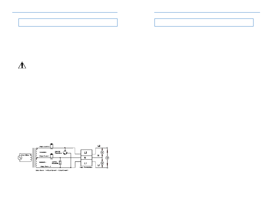
Current
Output Current #1 displays the true RMS current on N. If there are no 120
V loads connected to N-L2, then this current represents the 120 V loads on N-L1
plus any equipment connected to the 120 V output receptacles.
Output Current #2 displays the true RMS current on L2. This includes the
current flowing in L2 of the output terminal block, plus the current flowing in all 208
VAC or 240 VAC receptacles.
NOTE: The total RMS current displayed for L1 and L2 may be different than
the sum of the individual currents flowing in each output receptacle and
terminal block. This is because of potentially nonlinear loads which have
currents that are not inphase with each other.
Volt Amps
The apparent output power of the UPS calculated by multiplying output
voltage by the output current. The total UPS output VA may not equal the sum VA
drawn from the connected equipment. This is due to different power factor rating
for each piece of equipment.
Power in Watts
The real output power of the UPS calculated in Watts. This will be equal to
the sum of the real output power for all equipment connected to the UPS.
Power Factor
The ratio of true power (power actually consumed) to apparent power (simple
product of voltage and current) at the output of the UPS.
Line Frequency
The frequency of the AC Line measured at the output of the UPS.
Fig. 33
Output Parameter Measurement Points