Alera Lighting AL 1-Light User Manual
Al 1-light, Technical installation data
© 2014 Alera Lighting, a division of Hubbell Lighting, Inc. Because of continuing product improvement programs, Alera Lighting reserves the right to change specifications
without notice. 701 Millennium Blvd. Greenville, SC 29607 / Tel 864.678.1000 / Tech Support 864.678.1580 / Website www.aleralighting.com
Page 1/4 Rev. 01/14/14
RECESSED / AL 1-LIGHT TID
AL 1-LIGHT
Technical Installation Data
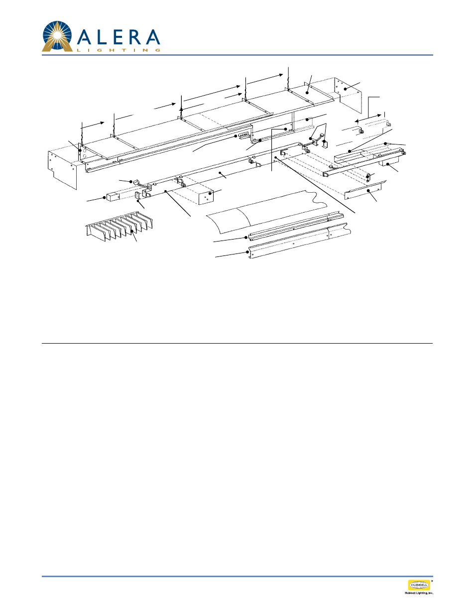
STRAIGHT RUN (VIEW SHOWN FROM WALL SIDE)
GENERAL
Work in this direction
1) Fasteners not provided for wall rail or wall plates.
2) All fasteners provided for housing, endplates, connector/aligners and electrical unit connections.
3) Pieces requiring a field cut:
Wall Rail (steel), Wall Plate (steel), Trim Rail (aluminum), Wireway
Cover (aluminum) and Diffusers (plastic or aluminum).
SAMPLE: AL-1T8-P-R-LD-EPU-19.11
Consists of:
(3) 92745 Wall Rails
(3) 92746 Wall Plates
(2) 97561-00 90" Housing
(1) 97561-04 21" Housing
(1) 97559-00 ADJ Housing
(6) 114084 Reflector
(2) AL8 1T8 EPU
(1) AL2 1T8 EPU L
(1) AL4 1T8 EPU ADJ
(6) 107945-04 Parabolic Louvers
(1) 97476-00 Electrical End Assembly
(2) 97416-00 End Row End Plates
STEP ONE—INSTALL WALL RAILS, PLATES, AND HOUSINGS
1) Install
wall rails (see next page), fasteners not provided.
2) Install
wall plates if required. Fasteners not provided.
3) Starting from right end of row (facing wall) install
endplate on first (shortest) housing with screws and nuts provided.
4) Install first (shortest)
housing and work to left installing progressively longer housings.
5) Top lip of
housings tip into upper hook form of wall rail. Secure housing firmly in place by flattening wall rail bend tab
over housing lip.
6) Connect hanging wires loosely.
7) Install each successive housing (shortest to longest) in similar manner, connecting housings with screws and nuts provided
and then hang loosely on hanging wires.
8) Also install
trim connector/aligners at each joint as row installation progresses.
9) Install endplate on adjustable housing. Slip adjustable
housing into last “fixed length” housing and hang entire assembly
as a unit. Adjustable housing is then pulled out to required dimension.
10) Square-cut
trim rail for adjustable housing to required length; drill three (3) each 7/32" holes using template provided
and install with sheet metal screws.
11) Level entire row on hanging wires.
Power Feed
21" Housing
90" Housing
Plug-in Connector
Service Cover
Power Access Only
Parabolic Louver
Wall Rail
Wall Plate
(where required)
Reflector
(where required)
Connector Plate
Trim Connector/
Aligner
Trim Rail,
cut to length
90" Housing
Adjustable
Housing
Adjustment
Endplate
17"
Adjustment
Wireway cover
(cut to length)
Cut
Clip
Cut
Endcaps
Electrical End
Assembly
AL8-1T8-EPU
8' Electrical Unit
AL4-1T8-EPU-ADJ
4' Adjustable
Electrical Unit
AL8-1T8-EPU
8' Electrical Unit
AL2-1T8-EPU-L
2' Electrical Unit
Electrical End
Assembly
Drill (3) holes
(template provided)
Lamp Shield
Hanging
Wires
Endplate