A+class, Occupancy sensor – Alera Lighting APCS OS User Manual
Page 3
Page 3/5 Rev. 07/16/13 H72-00436
IntegRated ContRols / A+CLASS
™
APCS OS TID
A+CLASS
™
OCCupAnCy SenSOr
Technical Installation Data
© 2013 alera lighting, a division of Hubbell lighting, Inc. Because of continuing product improvement programs, alera lighting reserves the right to change specifications
without notice. 701 Millennium Blvd. greenville, sC 29607 / tel 864.678.1000 / Website www.aleralighting.com
US Patent #8,436,542
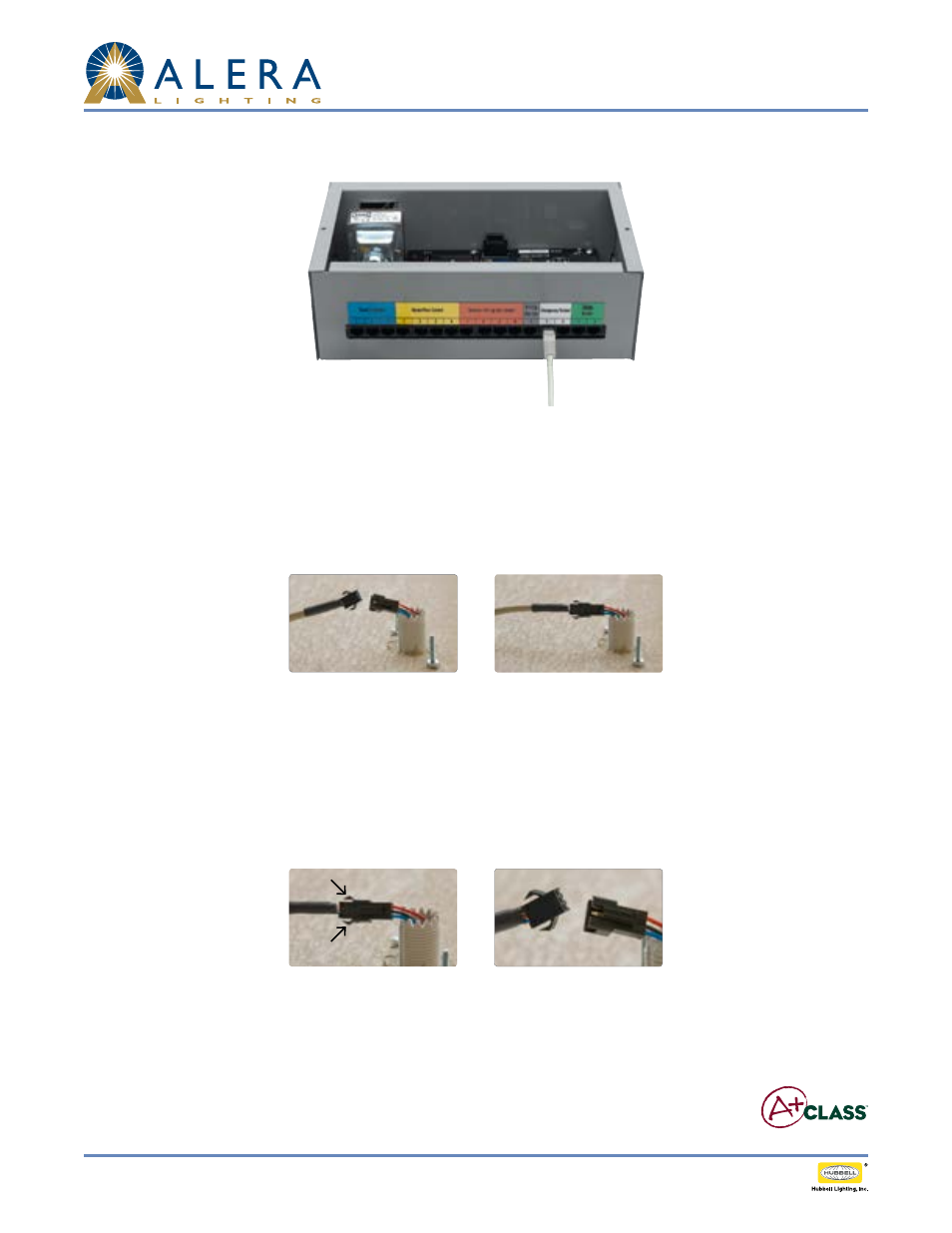
Fig. K
Fig. M
Fig. l
Fig. N
Fig. J
CCM low Voltage CAT5 Connector Ports (line voltage not visible in this image;
no line voltage connection required for occupancy sensor)
5. Route the White cable from the Classroom Control Module to the Occupancy sensor.
Note: low voltage wiring must be isolated from line voltage wiring. Consult National and local Electrical Codes for conduit requirements.
6. Plug the White cable QTI connector into the Occupancy sensor’s QTI connector (see Figures K and l).
7. Perform system setup and/or programming activities as applicable in accordance with the instructions of the Classroom Control Module.
8. Verify Occupancy sensor functionality by checking system status/Occupancy sensor on the Classroom Control Module.
Real-time occupied/unoccupied states will be displayed if operating properly. If occupancy states do not change, check wiring.
9. If desired, to disconnect Occupancy sensor from White CCM cable, press down on the upper tab on the connection (located on the White
cable side of the QTI connector). Gently pull the two sides of the QTI connector apart (see Figures M and N).
4. Plug the 50 ft. White CAT5 cable into either of the two available White connector ports on the Classroom Control Module (see Figure J).