Imba-h61a, Imbm-h61a chassis intrusion connector – AAEON IMBA-H61A User Manual
Page 28
IMBA-H61A
2-20
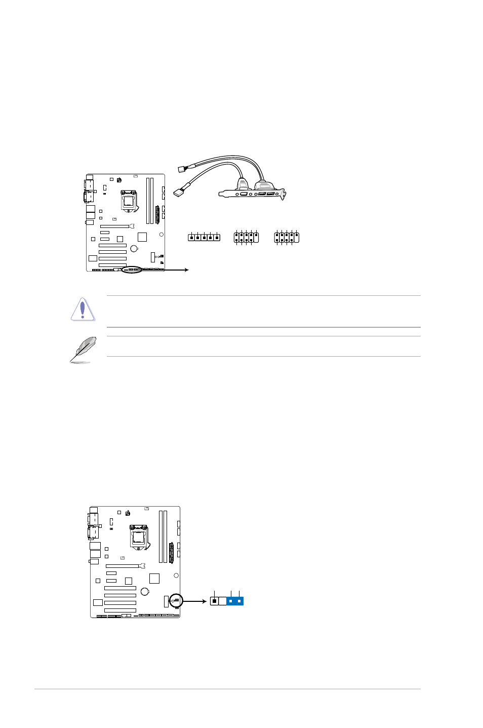
7. USB 2.0 connectors (10-1 pin USB89, USB45; 5-pin USB10)
These connectors are for USB 2.0 ports. Connect the USB module cable
to any of these connectors, then install the module to a slot opening at the
back of the system chassis. These USB connectors comply with USB 2.0
specification that supports up to 480 Mbps connection speed.
Never connect a 1394 cable to the USB connectors. Doing so will damage the
motherboard!
The USB module cable is purchased separately.
IMBA-H61A Front USB 2.0 Header connectors
+5V
USB9-
USB9+
GND
(NC)
+5V
USB8-
USB8+
GND
USB89
USB10
USB45
PIN 1
+5V
USB5-
USB5+
GND
(NC)
+5V
USB4-
USB4+
GND
PIN 1
PIN 1
+5V
USBD-
USBD+
GND
GND
GND
IMBM-H61A Chassis intrusion connector
No Intrudor
Intrudor Intrudor
PIN1
CHASSIS1
8. Chassis intrusion connector (4-1 pin CHASSIS1)
This connector is for a chassis-mounted intrusion detection sensor or switch.
Connect one end of the chassis intrusion sensor or switch cable to this
connector. The chassis intrusion sensor or switch sends a high-level signal to
this connector when a chassis component is removed or replaced. The signal
is then generated as a chassis intrusion event.
By default, the pins labeled “Intruder” are shorted with a jumper cap. Remove
the jumper caps only when you intend to use the chassis intrusion detection
feature.