How to calculate power generated, Power and flow charts calculation example, Cla-val – Cla-Val X143HP User Manual
Page 2: Technical data
Power = Volts * Amps. To calculate necessary amps, divide the necessary power by the supplied voltage. Both the load on the sys-
tem and the capacity of the power system is described in amp-hours. Multiply the amps by the number of hours the device runs per
day to calculate amp-hours. The generation capacity must be greater than the typical load on the system. The total site load is the
summation of each of the individual device requirements.
Excess system capacity is determined by subtracting the system load from the system generating capacity. System generating
capacity is determined by evaluating power in watts generated for a given head from the graph. Power in watts is then converted to
amps for a given voltage and multiplied by the run-time (WATTS / VOLTAGE = AMPS, AMPS x HOURS = AMP-HOURS). System
load must be less than the system generating capacity but may be exceeded temporarily, provided ample power is available in the
battery.
How to Calculate Power Generated
s
e
t
o
N
S
R
U
O
H
-
P
M
A
)
Y
A
D
/
N
I
M
(
e
m
i
T
n
u
R
C
D
V
2
1
@
S
P
M
A
)
S
T
T
A
W
(
*r
e
w
o
P
e
c
i
v
e
D
s
u
o
u
n
it
n
o
C
0
0
.
4
0
0
.
0
4
4
1
7
1
.
0
0
0
.
2
)
g
n
i
v
i
e
c
e
R
(
o
i
d
a
R
n
i
M
5
y
r
e
v
e
n
o
it
a
r
u
d
c
e
S
1
3
0
.
0
0
8
.
4
2
4
.
0
0
0
.
5
)
g
n
it
ti
m
s
n
a
r
T
(
o
i
d
a
R
s
u
o
u
n
it
n
o
C
0
0
.
0
3
0
0
.
0
4
4
1
5
2
.
1
0
0
.
5
1
U
T
R
e
l
b
a
i
r
a
V
3
3
.
8
0
0
.
0
3
7
6
.
6
1
0
0
.
0
0
2
p
m
u
P
y
l
n
O
g
n
i
c
i
v
r
e
S
3
3
.
3
0
0
.
0
6
3
3
.
3
0
0
.
0
4
p
m
a
L
t
n
e
c
s
e
r
uo
l
F
*All v alues are assumed and do not necessarily reflect actual v alues
TOTAL REQUIRED AMP-HOURS: 45.70
**
S
R
U
O
H
-
P
M
A
C
D
V
2
1
@
S
P
M
A
)
S
T
T
A
W
(
r
e
w
o
P
)I
S
P
(
e
r
u
s
s
e
r
P
t
u
p
t
u
O
)I
S
P
(
e
r
u
s
s
e
r
P
t
u
p
n
I
Pressure Drop (PSI)
0
0
.
0
2
2
6
1
.
9
110.00
0
0
.
0
4
0
0
.
0
2
0
0
.
0
6
**Assuming Generation Unit runs 24hours/day
TOTAL SUPPLIED AMP-HOURS: 220.00
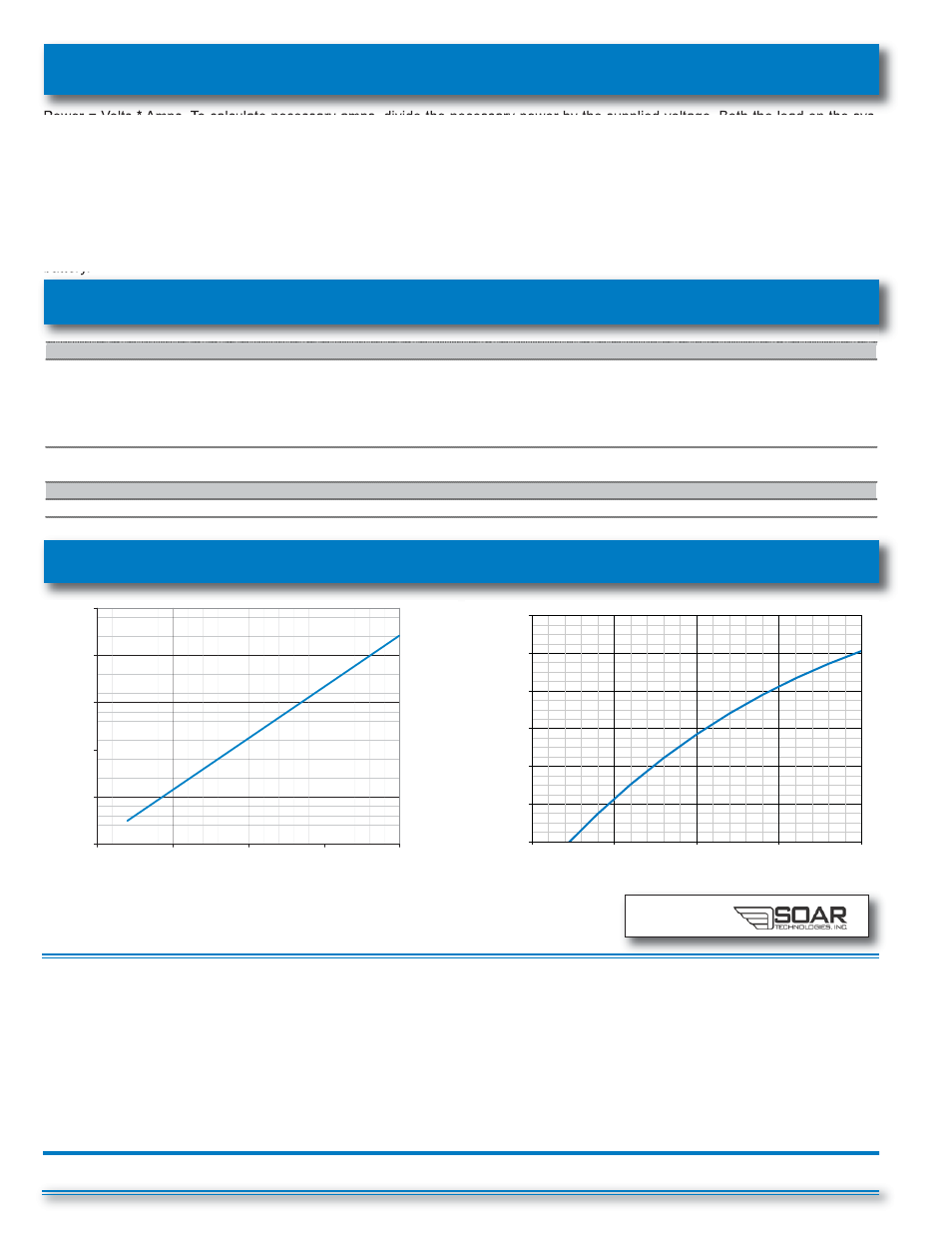
Power and Flow Charts
Calculation Example
Technical Data:
Both the power generated and flow through the Power Generator are dependent upon the differential pressure (DP) across the Power
Generator unit. To determine the DP, subtract downstream pressure from the upstream pressure. Use the calculated DP along with the
power/flow charts to estimate the power and flow of the Power Generator. If the flow through the Power Generator exceeds the down-
stream flow of the water system or a minimum DP is not met, the Power Generator will be inoperable. If the Differential Pressure across
the unit exceeds 60 PSID, the optional control valve must be used to limit the differential.
Battery storage capacity is variable upon each application and the customer’s needs. If instantaneous system load exceeds the power
supplied by the Power Generator, additional power will be drawn from the battery until battery supplies are depleted. Excess power pro-
duced by the generator during times of low load is diverted to the diversion load once the battery is fully charged.
E-X143HP (R-03/2014)
developed in
partnership with
0
50
100
150
200
250
20
30
40
50
60
Differential Pressure (psi)
P
owe
r (wa
tts
)
14
16
18
20
22
24
26
20 30 40 50 60
Flow (gpm)
Differential Pressure (psi)
Note: The curves shown above were produced utilizing the control valve downstream of the gen-
eration unit. For detailed power and flow calculations, please contact the factory at 800.942.6326
or the sales agent nearest you to perform an analysis using our Cla-Power® Software.
CLA-VAL
Copyright Cla-Val 2014 Printed in USA Specifications subject to change without notice.
P.O. Box 1325
• Newport Beach, CA 92659-0325 • Phone: 949-722-4800 • Fax: 949-548-5441 • E-mail: [email protected] • Website cla-val.com
©