Cla-Val 20-01/620-01 User Manual
Page 2
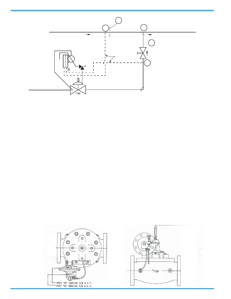
1.
Pressure at B is maintained equal to pressure at A within ±6 inches water pressure. This is accomplished by modulation of the
20-01 valve installed in the hi-pressure line.
2.
With pressure at B maintained equal to pressure at A, the differential pressure between B and C will be equal to the
differential pressure between A and C.
3.
Flow rate through secondary restriction R2 will be maintained in relation to the flow rate through primary restriction R1. The
proportional flow ratios will be directly rated to the capacities of restriction R1 and R2.
4.
Primary restriction at R1 can be fixed as shown, or can be adjustable the same as the secondary restriction at R2.
If the primary restriction at R1 is to be fixed, it must be calibrated in relation to two things:
A. Accuracy required at Minimum Flow Rate.
B. Systems allowable pressure loss at Maximum Flow Rate.
For example: Excellent control will result within approximately ±5% accuracy when a 60" water differential is created across the
fixed restriction (R1).As the flow across this restriction increases, the accuracy (in % of flow) also increases. As the flow across the
restriction (R1) decreases, the accuracy (in % of flow) slightly decreases.
Therefore, where accuracy of ±5% or less is required over a wide flow range, at least a 60" water differential should be created
across the fixed restriction (R 1) at the lowest flow rate. In sizing the adjustable restriction (R2), consideration must be given to two
things:
A. Ratio of blend (flow through R2 as compared to flow through R1).
B. Differential across R1.
To obtain a blend ratio of 1 to 1, the differential created by R2, when adjusted to "full open", must not be more than the differential
created by R1 when passing an equal flow.
Where the blend ratio requires less flow at R2 than at R1, the differential created by R2 at "full open" can be proportionally more
than the differential created by R1 at an equal flow rate.
Where the blend ratio requires more flow at R2 than at R1, the differential created by R2 at "full open" must be proportionally less than
the differential created by R1 at an equal flow rate.
FIXED ORIFICE
OR RESTRICTION
BLENDING POINT
SUPPLY LINE NO. 1
LOW PRESSURE
BLENDED PRODUCT
VARIABLE DEMAND
THROTTLING
VALVE
SENSING
LINES
R1
A
R2
B
CLA-VAL 20-01
BLENDING VALVE
SUPPLY LINE NO. 2
HIGH PRESSURE
C
S
2
D
A
Operations