Cla-val – Cla-Val DBF Series User Manual
Page 2
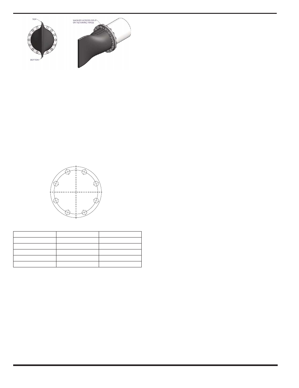
2. Lift the duckbill check valve into position and align the bolt
holes of the pipe flange, check valve flange and the retaining ring.
Ensure the check valve’s bill is oriented in a vertical position or as
nearly vertical as is possible (rotate if limited ground clearance is
available).
Note: For Duckbill Check Valves 14” and larger, we recommend
nylon slings be used for lifting valves into position during installation.
3. After the duckbill check valve and retaining ring are in the cor-
rect position, push two (2) bolts through to ensure alignment. After
the proper alignment has been obtained, install remaining bolts
and nuts, using washers at the split holes - if the Check Valve
comes with a retaining ring (See Figure 3).
4. Use two wrenches to prevent torque when installing the
Check Valve. Tighten all flange bolts in a criss-cross pattern simi-
lar to the one shown in Figure 4 to the maximum torque recom-
mended in Figure 5.
5. Do not weld near the Check Valve.
1
Torque settings as recommended by the Fluid Sealing
Association Std FSA-PSJ-702-06 “Rubber Flanged Non-Metallic
Expansion Joint Installation, Maintenance and Storage” Manual
Figure 5
Notes:
a) To prevent leakage, the flange bolts should be retightened after
one week of operation and checked periodically thereafter.
b) Torque values are approximate. After installation the system
should be pressurized and examined to confirm a proper seal. For
hydrostatic systems, torque values may need to be increased.
IMPORTANT NOTE:
Debris caught under the valve can potentially effect its operation.
Therefore, make certain there is 6” of ground clearance between
the bill of the valve and the ground during and after installation.
Installation Problems:
If the valve does not fit properly:
• During the installation, if fit appears to be a problem, contact your
Cla-Val Regional Office or Cla-Val Factory.
If the valve will not close fully or check flow in the reverse
direction:
• Possible obstruction in the line. Inspect the valve for entrapped
foreign objects, which may have lodged between the lips of the
valve.
• Insufficient clearance may exist below the valve (forcing it open).
Verify there is clearance between the bottom of the bill and the
ground and that no debris is trapped between the ground and the
valve bottom.
• The backpressure may not be sufficient to seal the bill completely.
If the valve leaks between the flanges:
• Check that all bolts are sufficiently tightened. Increase the torque
on all bolts by 5 ft-lbs in a cross pattern. Continue this procedure
until the leakage stops.
• Check that no foreign material has become lodged between the
mating flanges.
Maintenance:
• Periodically, an inspection should be performed to verify the
valve’s performance.
• If a build up of debris occurs within the valve, line pressure should
flush it out. In some instances, a wooden plank 1” x 4” or 1½” x
12” may be temporarily inserted into the bill of the valve and rotat-
ed 90°. This will clear the check valve of any debris that may be
trapped in the bill.
• A periodic visual inspection of the valve is also a good idea.
Inspect the tube and cover for cuts, checking, and fissures. Do not
be alarmed if small cuts have formed in the outer cover. If neces-
sary, repairs can be made on site with a repair compound. If sig-
nificant fissures are noticed where fabric is exposed and torn, the
valve must be replaced. Upon inspection of the inside of the bill, if
blisters, deformation, or delamination is noted, this is an indication
that the media or higher than expected temperatures are attacking
the tube. The valve should be replaced as soon as possible.
Further research into the actual operating conditions (media &
temperature), is required so that a more appropriate check valve
may be supplied. Please contact your Cla-Val Regional Office or
Cla-Val Factory to discuss any concerns you may have regarding
duckbill check valves.
Additional Tips:
• Do not modify the valve without first consulting Cla-Val. Doing so
would void your warranty.
• Do not over-torque flange bolts.
• Use metal washers - at least where the bolts go through the
retaining ring split holes. Keep the valve in its proper shipping
package and in an upright position until ready for installation.
• Tighten the valve flange bolts evenly.
CLA-VAL
Copyright Cla-Val 2008 Printed in USA Specifications subject to change without notice.
P.O. Box 1325
• Newport Beach, CA 92659-0325 • Phone: 949-722-4800 • Fax: 949-548-5441 • E-mail: [email protected] • Website cla-val.com
©
N-DBF
Pipe Size ID (in)
Torque (ft-lbs)
Torque (Nm)
1 - 2
20
27
2.5 - 5
25
34
6 - 12
35
48
14 - 18
50
68
20 and larger
60
82
1
7
5
3
8
2
6
4
Figure 3
Figure 4
Figure 5