Cla-val, When ordering, please specify, Pilot system specifications – Cla-Val 85-09-1/685-09-1 User Manual
Page 4
We recommend providing adequate space around valve for maintenance work
PO Box 1325 Newport Beach CA 92659-0325
Phone: 949-722-4800
Fax: 949-548-5441
CLA-VAL
CLA-VAL CANADA
CLA-VAL EUROPE
4687 Christie Drive
Beamsville, Ontario
Canada L0R 1B4
Phone: 905-563-4963
Fax: 905-563-4040
Chemin dés Mesanges 1
CH-1032 Romanel/
Lausanne, Switzerland
Phone: 41-21-643-15-55
Fax: 41-21-643-15-50
©
COPYRIGHT CLA-VAL 2011 Printed in USA
Specifications subject to change without notice.
www.cla-val.com
E-85-09-1/685-09-1 (R-4/2011)
Represented By:
When Ordering,
Please Specify
1. Catalog No. 85-09-1 or
No. 685-09-1
2. Valve Size
3. Pattern - Globe or Angle
4. Pressure Class
5. Threaded, Flanged or
Grooved End
6. Trim Material
7. Desired Options
8. When Vertically Installed
Note: For main valve option
descriptions, refer to 100-02 (61-
02) or 100-21 (661-02) Technical
Data Sheets.
Temperature Range
Water to 180°F Max
Materials
Standard Pilot System Materials
Pilot Control: Bronze ASTM B62
Trim: Stainless Steel Type 303
Rubber: Buna-N
®
Synthetic Rubber
Optional Pilot System Materials
Pilot Systems are available with optional
Aluminum, Stainless Steel or Monel
materials at additional cost.
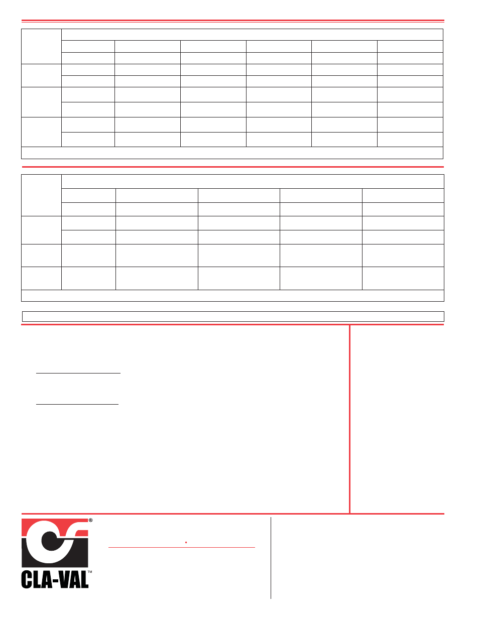
Pilot System Specifications
85-09-1
Valve
Selection
100-02 Pattern:
Globe (G), Angle (A),
End Connections:
Threaded (T), Grooved (GR), Flanged (F) Indicate Available Sizes
Inches
2
1
⁄
2
3
4
6
8
mm
65
80
100
150
200
Basic Valve
100-02
Pattern
G, A
G, A
G, A
G, A
G, A
End Detail
T ,F, Gr*
T, F, Gr
F, Gr
F, Gr*
F, Gr*
Suggested
Flow
(gpm)
Maximum
300
460
800
1800
3100
Max. Intermittent
670
1000
1800
4000
7000
Suggested
Flow
(Liters/Sec)
Maximum
19
29
50
113
195
Max. Intermittent
42
63
113
252
441
100-01 Series is the full internal port Hytrol. *
Globe Grooved Only
685-09-1
Valve
Selection
100-21 Pattern:
Globe (G), Angle (A),
End Connections:
Threaded (T), Grooved (GR), Flanged (F) Indicate Available Sizes
Inches
3
4
6
8
mm
80
100
150
200
Basic Valve
100-21
Pattern
G
G, A
G, A
G, A
End Detail
F
F
F
F
Suggested
Flow
(gpm)
Maximum
260
580
1025
2300
Suggested
Flow
(Liters/Sec)
Maximum
16
37
65
145
100-20 Series is the reduced internal port size version of the 100-01 Series.