Cla-val, Dimensions model 100s – Cla-Val 90-42 User Manual
Page 10
(MAX)
GGGG
DDDD
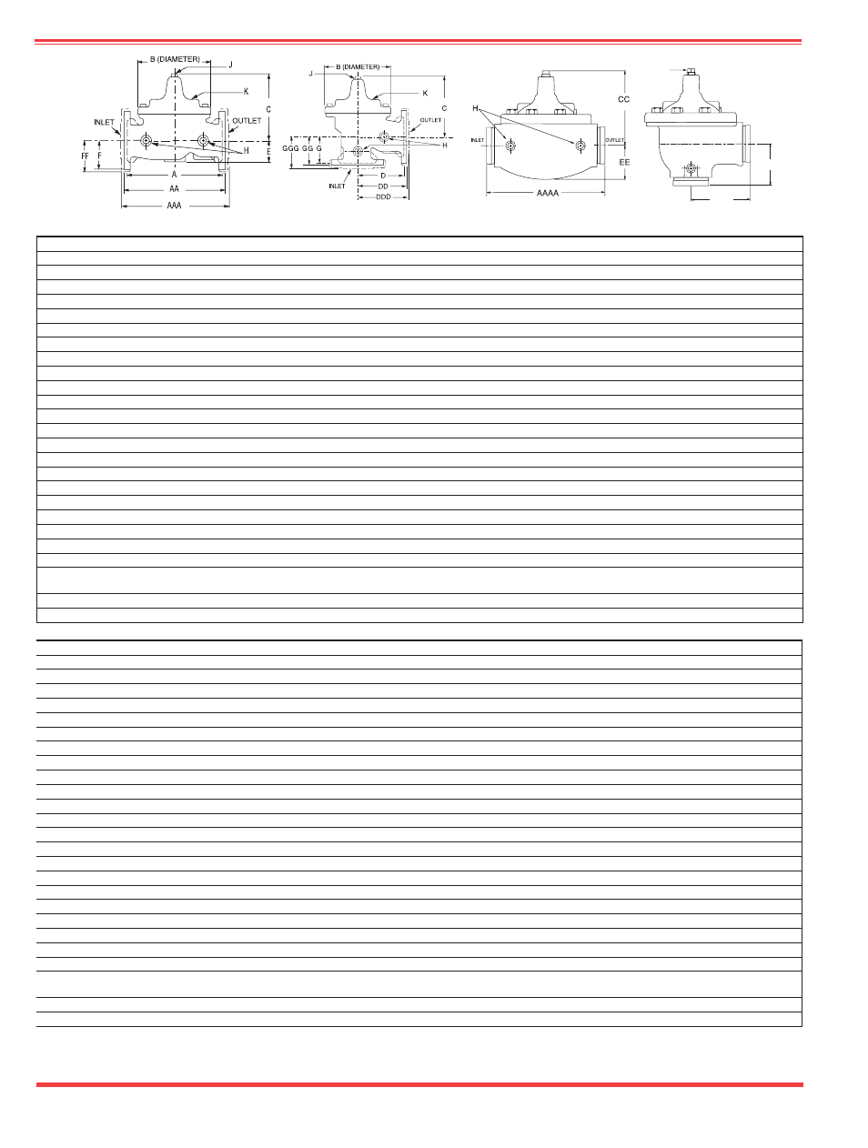
OUTLET
INLET
J
100S (Globe)
2100S (Angle)
100S Grooved (Globe)
2100S Grooved (Angle)
Dimensions
Model 100S
CLA-VAL
Copyright Cla-Val 2008 Printed in USA Specifications subject to change without notice.
P.O. Box 1325
• Newport Beach, CA 92659-0325 • Phone: 949-722-4800 • Fax: 949-548-5441 • E-mail: [email protected] • Website cla-val.com
©
E-100S/2100S (R-11/06)
Cla-Val Control Valves operate with maximum efficiency when mounted in horizontal piping with the main valve cover UP, however, other positions are acceptable. Due to
component size and weight of 8 inch and larger valves, installation with cover UP is advisable. We recommend isolation valves be installed on inlet and outlet for maintenance.
Adequate space above and around the valve for service personnel should be considered essential. A regular maintenance program should be established based on the specific
application data. However, we recommend a thorough inspection be done at least once a year. Consult factory for specific recommendations.
*1
1
⁄
2"
Size Only
*40mm Size Only
Valve Size
(Inches)
3
⁄
8
1
⁄
2
-
3
⁄
4
1
1
1
⁄
4
-1
1
⁄
2
2
2
1
⁄
2
3
4
6
8
10
12
14
16
24
36
A Threaded
2.75
3.50
5.12
7.25
9.38
11.00 12.50
—
—
—
—
—
—
—
—
—
AA 150 ANSI
—
—
—
8.50*
9.38
11.00 12.00 15.00
20.00
25.38
29.75
34.00
39.00
41.38
61.50
76.00
AAA 300 ANSI
—
—
—
9.00*
10.00 11.62 13.25 15.62
21.00
26.38
31.12
35.50
40.50
43.50
63.24
78.00
AAAA Grooved End
—
—
—
8.50
9.00
11.00 12.50 15.00
20.00
25.38
—
—
—
—
—
—
B Dia.
2.50
3.12
4.38
5.62
6.62
8.00
9.12
11.50
15.75
20.00
23.62
28.00
32.75
35.50
53.16
66.00
C Max.
2.00
3.00
2.75
5.50
6.50
7.56
8.19
10.62
13.38
16.00
17.12
20.88
24.19
25.00
43.93
61.50
CC Max. Grooved End
—
—
—
4.75
5.75
6.88
7.25
9.62
12.12
14.62
—
—
—
—
—
—
D Threaded
—
—
—
3.25
4.75
5.50
6.25
—
—
—
—
—
—
—
—
—
DD 150 ANSI
—
—
—
4.00*
4.75
5.50
6.00
7.50
10.00
12.75
14.88
17.00
19.50
20.81
—
—
DDD 300 ANSI
—
—
—
4.25*
5.00
5.88
6.38
7.88
10.50
13.25
15.56
17.75
20.25
21.62
—
—
DDDD Grooved End
—
—
—
—
4.75
—
6.00
7.50
—
—
—
—
—
—
—
—
E
1.25
0.88
1.63
1.12
1.50
1.69
2.56
3.19
4.31
5.31
9.25
10.75
12.62
15.50
17.75
24.56
EE Grooved End
—
—
—
2.00
2.50
2.88
3.12
4.25
6.00
7.56
—
—
—
—
—
—
F 150 ANSI
—
—
—
2.50
3.00
3.50
3.75
4.50
5.50
6.75
8.00
9.50
10.50
11.75
19.25
28.00
FF 300 ANSI
—
—
—
3.06
3.25
3.75
4.13
5.00
6.25
7.50
8.75
10.25
11.50
12.75
—
—
G Threaded
—
—
—
1.88
3.25
4.00
4.50
—
—
—
—
—
—
—
—
—
GG 150 ANSI
—
—
—
4.00*
3.25
4.00
4.00
5.00
6.00
8.00
8.62
13.75
14.88
15.69
—
—
GGG 300 ANSI
—
—
—
4.25*
3.50
4.31
4.38
5.31
6.50
8.50
9.31
14.50
15.62
16.50
—
—
GGGG Grooved End
—
—
—
—
3.25
—
4.25
5.00
—
—
—
—
—
—
—
—
H NPT Body Tapping
—
1
⁄
8
1
⁄
4
3
⁄
8
3
⁄
8
1
⁄
2
1
⁄
2
3
⁄
4
3
⁄
4
1
1
1
1
1
1
2
J NPT Cover Center Plug
1
⁄
8
1
⁄
8
1
⁄
4
1
⁄
4
1
⁄
2
1
⁄
2
1
⁄
2
3
⁄
4
3
⁄
4
1
1
1
1
⁄
4
1
1
⁄
2
2
1
1
⁄
2
2
K NPT Cover Tapping
—
1
⁄
8
1
⁄
4
3
⁄
8
3
⁄
8
1
⁄
2
1
⁄
2
3
⁄
4
3
⁄
4
1
1
1
1
1
1
2
Valve Stem Internal
Thread UNF
—
—
—
10-32 10-32 10-32
1
⁄
4
-28
1
⁄
4
-28
3
⁄
8
-24
3
⁄
8
-24
3
⁄
8
-24
3
⁄
8
-24
3
⁄
8
-24
1
⁄
2
-20
3
⁄
4
-16
3
⁄
4
-16
Stem Travel
—
—
—
0.4
0.6
0.7
0.8
1.1
1.7
2.3
2.8
3.4
4.0
4.5
6.75
10.12
Approx. Ship Wt. Lbs.
3
3
8
15
35
50
70
140
285
500
780
1165
1600
2265
6200
11470
Valve Size
(mm)
10
15-20
25
32-40
50
65
80
100
150
200
250
300
350
400
600
900
A Threaded
70
89
130
184
238
279
318
—
—
—
—
—
—
—
—
—
AA 150 ANSI
—
—
—
216*
238
279
305
381
508
645
756
864
991
1051
1562
1930
AAA 300 ANSI
—
—
—
229*
254
295
337
397
533
670
790
902
1029
1105
1606
1981
AAAA Grooved End
—
—
—
216
228
279
318
381
508
645
—
—
—
—
—
—
B Dia.
64
80
111
143
168
203
232
292
400
508
600
711
832
902
1350
1676
C Max.
51
76
70
140
165
192
208
270
340
406
435
530
614
635
1116
1562
CC Max. Grooved End
—
—
—
120
146
175
184
244
308
371
—
—
—
—
—
—
D Threaded
—
—
—
83
121
140
159
—
—
—
—
—
—
—
—
—
DD 150 ANSI
—
—
—
102*
121
140
152
191
254
324
378
432
495
528
—
—
DDD 300 ANSI
—
—
—
108*
127
149
162
200
267
337
395
451
514
549
—
—
DDDD Grooved End
—
—
—
—
121
—
152
191
—
—
—
—
—
—
—
—
E
32
23
42
29
38
43
65
81
110
135
235
273
321
394
451
624
EE Grooved End
—
—
—
52
64
73
79
108
152
192
—
—
—
—
—
—
F 150 ANSI
—
—
—
64
76
89
95
114
140
171
203
241
267
298
489
711
FF 300 ANSI
—
—
—
78
83
95
105
127
159
191
222
260
292
324
—
—
G Threaded
—
—
—
48
83
102
114
—
—
—
—
—
—
—
—
—
GG 150 ANSI
—
—
—
102*
83
102
102
127
152
203
219
349
378
399
—
—
GGG 300 ANSI
—
—
—
102*
89
110
111
135
165
216
236
368
397
419
—
—
GGGG Grooved End
—
—
—
—
83
—
108
127
—
—
—
—
—
—
—
—
H NPT Body Tapping
—
1
⁄
8
1
⁄
4
3
⁄
8
3
⁄
8
1
⁄
2
1
⁄
2
3
⁄
4
3
⁄
4
1
1
1
1
1
1
2
J NPT Cover Center Plug
1
⁄
8
1
⁄
8
1
⁄
4
1
⁄
4
1
⁄
2
1
⁄
2
1
⁄
2
3
⁄
4
3
⁄
4
1
1
1
1
⁄
4
1
1
⁄
2
2
1
1
⁄
2
2
K NPT Cover Tapping
—
1
⁄
8
1
⁄
4
3
⁄
8
3
⁄
8
1
⁄
2
1
⁄
2
3
⁄
4
3
⁄
4
1
1
1
1
1
1
2
Valve Stem Internal
Thread UNF
—
—
—
10-32 10-32 10-32
1
⁄
4
-28
1
⁄
4
-28
3
⁄
8
-24
3
⁄
8
-24
3
⁄
8
-24
3
⁄
8
-24
3
⁄
8
-24
1
⁄
2
-20
3
⁄
4
-16
3
⁄
4
-16
Stem Travel
—
—
—
10
15
18
20
28
43
58
71
86
102
114
171
257
Approx. Ship Wt. Kgs.
1.4
1.4
4
7
16
23
32
64
129
227
354
528
726
1027
2812
5200