Cla-val, Purchase specifications dimensions, Valve capacity – Cla-Val 50-20 User Manual
Page 6
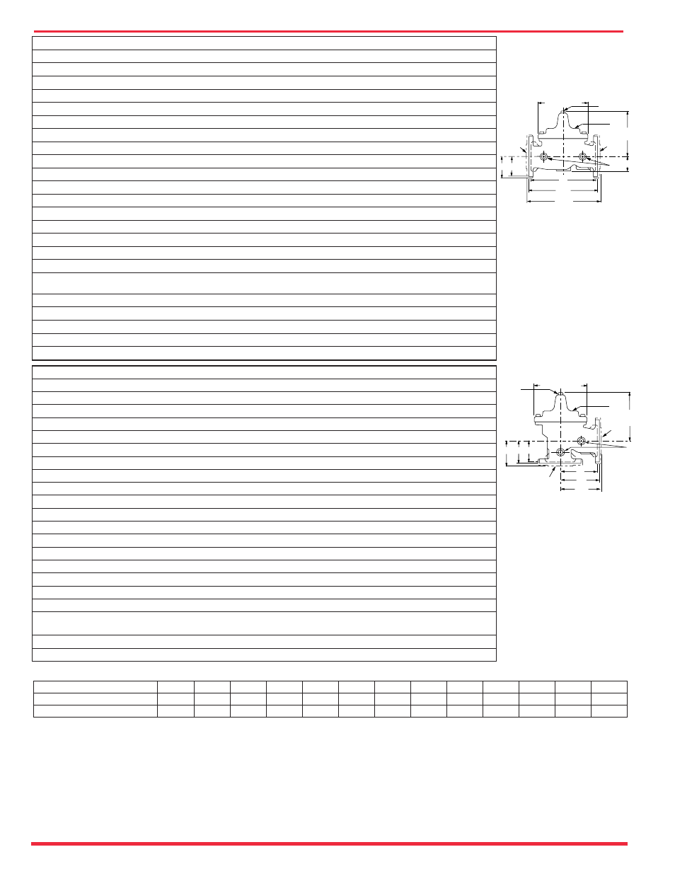
OUTLET
A
AA
AAA
E
INLET
H
J
B (DIAMETER)
K
FF F
C
DDD
DD
INLET
OUTLET
C
H
B (DIAMETER)
K
GG
GGG
G
D
J
The Fire Pump Pressure Relief Valve shall modulate to relieve excess pressure
in a fire protection system. It shall maintain constant pressure in the system
regardless of demand changes. It shall be pilot controlled and back pressure
shall not affect its set point. It shall be actuated by line pressure through a pilot
control system and open fast in order to maintain steady system pressure as
system demand decreases. It shall close gradually to control surges and shall
re-seat drip-tight within 5% of its pressure setting. The main valve shall be of
the hydraulically-operated, pilot-controlled, diaphragm-type, globe or angle
valve. It shall have a single, removable, teflon-coated seat. Internal and exter-
nal epoxy coating, a stem guided at both ends, and a resilient disc with a rec-
tangular cross section, being contained on 3 1/2 sides. No external packing
glands shall be permitted and the diaphragm shall not be used as a seating sur-
face. The pilot control shall be a direct-acting, adjustable, spring-loaded,
diaphragm-type valve designed for modulating service to permit flow when
controlling pressure exceeds spring setting. It shall be the MODEL 50G-20
(globe) or Model 50A-20 (angle) Pressure Relief Valve as manufactured by
Cla-Val, Newport Beach, California.
Purchase Specifications
Dimensions
We recommend providing
adequate space around
valve for maintenance work.
Valve Size
(Inches)
1
1
⁄
2
2
2
1
⁄
2
3
4
6
8
10
12
14
16
24
36
A Threaded
7.25
9.38 11.00 12.50
—
—
—
—
—
—
—
—
—
AA 150 ANSI
8.50* 9.38 11.00 12.00 15.00 20.00 25.38 29.75 34.00 39.00 41.38 61.50 76.00
AAA 300 ANSI
9.00* 10.00 11.62 13.25 15.62 21.00 26.38 31.12 35.50 40.50 43.50 63.24 78.00
B Dia.
5.62
6.62
8.00
9.12 11.50 15.75 20.00 23.62 28.00 32.75 35.50 53.16 66.00
C Max.
5.50
6.50
7.56
8.19 10.62 13.38 16.00 17.12 20.88 24.19 25.00 43.93 61.50
D Threaded
3.25
4.75
5.50
6.25
—
—
—
—
—
—
—
—
—
DD 150 ANSI
4.00* 4.75
5.50
6.00
7.50 10.00 12.75 14.88 17.00 19.50 20.81
—
—
DDD 300 ANSI
4.25* 5.00
5.88
6.38
7.88 10.50 13.25 15.56 17.75 20.25 21.62
—
—
E
1.12
1.50
1.69
2.56
3.19
4.31
5.31
9.25 10.75 12.62 15.50 17.75 24.56
F 150 ANSI
2.50
3.00
3.50
3.75
4.50
5.50
6.75
8.00
9.50 10.50 11.75 19.25 28.00
FF 300 ANSI
3.06
3.25
3.75
4.13
5.00
6.25
7.50
8.75 10.25 11.50 12.75
—
—
G Threaded
1.88
3.25
4.00
4.50
—
—
—
—
—
—
—
—
—
GG 150 ANSI
4.00* 3.25
4.00
4.00
5.00
6.00
8.00
8.62 13.75 14.88 15.69
—
—
GGG 300 ANSI
4.25* 3.50
4.31
4.38
5.31
6.50
8.50
9.31 14.50 15.62 16.50
—
—
H NPT Body Tapping
3
⁄
8
3
⁄
8
1
⁄
2
1
⁄
2
3
⁄
4
3
⁄
4
1
1
1
1
1
1
2
J NPT Cover Center Plug
1
⁄
4
1
⁄
2
1
⁄
2
1
⁄
2
3
⁄
4
3
⁄
4
1
1
1
1
⁄
4
1
1
⁄
2
2
1
1
⁄
2
2
K NPT Cover Tapping
3
⁄
8
3
⁄
8
1
⁄
2
1
⁄
2
3
⁄
4
3
⁄
4
1
1
1
1
1
1
2
Valve Stem Internal
Thread UNF
10-32 10-32 10-32
1
⁄
4
-28
1
⁄
4
-28
3
⁄
8
-24
3
⁄
8
-24
3
⁄
8
-24
3
⁄
8
-24
3
⁄
8
-24
1
⁄
2
-20
3
⁄
4
-16
3
⁄
4
-16
Stem Travel
0.4
0.6
0.7
0.8
1.1
1.7
2.3
2.8
3.4
4.0
4.5
6.75 10.12
Approx. Ship Wt. Lbs.
15
35
50
70
140
285
500
780
1165 1600 2265 6200 11470
X Pilot System
11.00 13.00 14.00 15.00 17.00 29.00 31.00 33.00 36.00 40.00 40.00 68.00 86.00
Y Pilot System
9.00
9.00 10.00 11.00 12.00 20.00 22.00 24.00 26.00 29.00 30.00 39.00 45.00
Z Pilot System
9.00
9.00 10.00 11.00 12.00 20.00 22.00 24.00 26.00 29.00 30.00 39.00 45.00
Valve Size
(mm)
40
50
65
80
100
150
200
250
300
350
400
600
900
A Threaded
184
238
279
318
—
—
—
—
—
—
—
—
—
AA 150 ANSI
216*
238
279
305
381
508
645
756
864
991
1051 1562 1930
AAA 300 ANSI
229*
254
295
337
397
533
670
790
902
1029 1105 1606 1981
B Dia.
143
168
203
232
292
400
508
600
711
832
902
1350 1676
C Max.
140
165
192
208
270
340
406
435
530
614
635
1116 1562
CC Max.
104
127
—
165
223
281
—
—
—
—
—
—
—
D Threaded
83
121
140
159
—
—
—
—
—
—
—
—
—
DD 150 ANSI
102*
121
140
152
191
254
324
378
432
495
528
—
—
DDD 300 ANSI
108*
127
149
162
200
267
337
395
451
514
549
—
—
E
29
38
43
65
81
110
135
235
273
321
394
451
624
F 150 ANSI
64
76
89
95
114
140
171
203
241
267
298
489
711
FF 300 ANSI
78
83
95
105
127
159
191
222
260
292
324
—
—
G Threaded
48
83
102
114
—
—
—
—
—
—
—
—
—
GG 150 ANSI
102*
83
102
102
127
152
203
219
349
378
399
—
—
GGG 300 ANSI
102*
89
110
111
135
165
216
236
368
397
419
—
—
H NPT Body Tapping
3
⁄
8
3
⁄
8
1
⁄
2
1
⁄
2
3
⁄
4
3
⁄
4
1
1
1
1
1
1
2
J NPT Cover Center Plug
1
⁄
4
1
⁄
2
1
⁄
2
1
⁄
2
3
⁄
4
3
⁄
4
1
1
1
1
⁄
4
1
1
⁄
2
2
1
1
⁄
2
2
K NPT Cover Tapping
3
⁄
8
3
⁄
8
1
⁄
2
1
⁄
2
3
⁄
4
3
⁄
4
1
1
1
1
1
1
2
Valve Stem Internal
Thread UNF
10-32 10-32 10-32
1
⁄
4
-28
1
⁄
4
-28
3
⁄
8
-24
3
⁄
8
-24
3
⁄
8
-24
3
⁄
8
-24
3
⁄
8
-24
1
⁄
2
-20
3
⁄
4
-16
3
⁄
4
-16
Stem Travel
10
15
18
20
28
43
58
71
86
102
114
171
257
Approx. Ship Wt. Kgs.
7
16
23
32
64
129
227
354
528
726
1027 2812 5200
CLA-VAL
Copyright Cla-Val 2007 Printed in USA Specifications subject to change without notice.
P.O. Box 1325
• Newport Beach, CA 92659-0325 • Phone: 949-722-4800 • Fax: 949-548-5441 • E-mail: [email protected] • Website cla-val.com
©
E-50-20 (R-5/07)
Valve Size (inches)
1 1/2
2
2 1/2
3
4
6
8
10
12
14
18
24
36
Max. Continuous GMP
125
208
300
460
800
1800
3100
4900
7000
8500
11000
25000
50000
Max Surge GPM
280
470
670
1000
1800
4000
7000
11000
16000
19000
25000
56500
85000
Valve Capacity