Specifications: seawater service option, Specifications, Dimensions – Cla-Val 50B-4KG1/2050B-4KG1 Technical Manual User Manual
Page 17: Purchase specifications, Valve capacity, Cla-val
PO Box 1325 Newport Beach CA 92659-0325
Phone: 949-722-4800
Fax: 949-548-5441
Web Site: cla-val.com
E-mail: [email protected]
CLA-VAL
CLA-VAL CANADA
CLA-VAL EUROPE
4687 Christie Drive
Beamsville, Ontario
Canada L0R 1B4
Phone: 905-563-4963
Fax: 905-563-4040
E-Mail: [email protected]
Chemin des M
ésanges 1
CH-1032 Romanel/
Lausanne, Switzerland
Phone: 41-21-643-15-55
Fax: 41-21-643-15-50
E-Mail: [email protected]
Copyright CLA-VAL 2014 Printed in USA Specifications subject to change without notice.
CLA-VAL UK
Dainton House, Goods Station Road
GB - Tunbridge Wells
Kent TN1 2 DH England
Phone: 44-1892-514-400
Fax: 44-1892-543-423
E-Mail: [email protected]
©
Represented By:
Specifications: Seawater Service Option
Sizes
Globe: 2" - 8" flanged
Angle: 2" - 8" flanged
Consult factory for flange ratings.
See page 1 for seawater service materials options.
E-50B-4KG1/2050B-4KGL1 (R-04/2014)
Model 2050B-4KG1 Angle
Model 50B-4KG1 Globe
We recommend providing adequate space around valve for maintenance work.
Specifications
Globe: 2" - 10” flanged
Angle: 2" - 10" flanged
150 and 300 ANSI B16.42
class - 175 psi Max.
class - 300 psi Max
Water, to 180°F Max.
Main Valve Body & Cover
Ductile Iron ASTM A536 Grade 65-45-12
Standard Main Valve Trim:
Bronze Seat, Teflon Coated
Stainless Steel Stem, Dura-Kleen Stem
Standard Pilot Control System:
Cast Bronze with
Stainless Steel trim
Available in the following relief
pressure ranges:
20-200 psi (150 Class)
100-300 psi (300 Class)
Protective epoxy resin coating
of wetted surfaces of main
valve cast iron components
(UL listed HNFX EX2855)
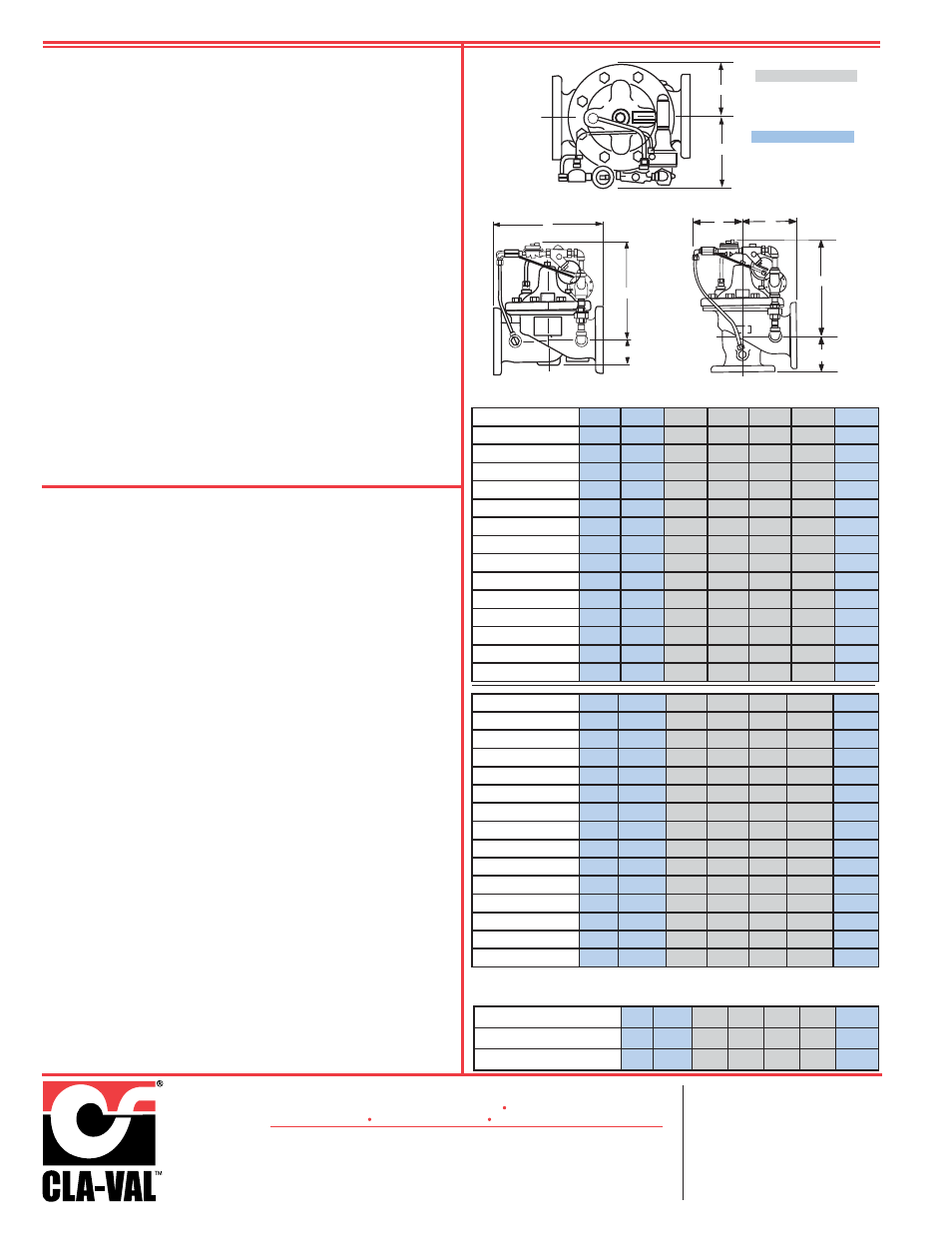
Dimensions
B
G
C
F
H
E
C
D
A
The Fire Pump Pressure Relief Valve shall modulate to relieve excess
pressure in a fire protection system. It shall maintain constant pressure
in the system regardless of demand changes. It shall be pilot controlled
and back pressure shall not affect its set point. It shall be actuated by
line pressure through a pilot control system and open fast in order to
maintain steady system pressure as system demand decreases. It shall
close gradually to control surges and shall re-seat drip-tight within 5% of
its pressure setting. The main valve shall be of the hydraulically-operat-
ed, pilot-controlled, diaphragm-type, globe or angle valve. It shall have
a single, removable, teflon-coated seat, a grooved stem guided at both
ends, and a resilient disc with a rectangular cross section, being con-
tained on 3 1/2 sides. No external packing glands shall be permitted and
the diaphragm shall not be used as a seating surface. The pilot control
shall be a direct-acting, adjustable, spring-loaded, diaphragm-type valve
designed for modulating service to permit flow when controlling pressure
exceeds spring setting. This valve shall be UL Listed and Factory Mutual
approved. It shall be the Model 50B-4KG1 (globe) or Model 2050B-
4KG1 (angle) Pressure Relief Valve as manufactured by Cla-Val Newport
Beach, California.
*Special Note:
The Model 50B-4KG1 Pressure Relief Valve is available with 300# ANSI
inlet flange and 150# ANSI outlet flange. This valve is used on higher
pressure systems where 300# flange connections are required, and
allows for adapting of a discharge cone (generally supplied with 150#
flange) to accommodate "atmospheric break" at relief valve discharge.
This relief valve, with 300# / 150# flanges is available on special order,
and is UNDERWRITERS LABORATORIES LISTED AND FACTORY
MUTUAL APPROVED.
Purchase Specifications
Sizes
End Details
Pressure Ratings
Standard Materials
Adjustment Range
Optional
Valve Capacity
Valve Sizes in Inches:
2"
2 1/2"
3"
4"
6"
8"
10"
NFPA 20 Maximum
Recommended GPM
208
300
500 1000 2500 5000 11000
= U.L., F.M. and
ULC sizes
Valve Size
(inches)
2”
2-1/2”
3”
4”
6”
8”
10”
Threaded Ends
9.38
11.00
12.50
- - -
- - -
- - -
- - -
A 150 Flanged
9.38
11.00
12.00
15.00
20.00
25.38
29.75
300 Flanged
10.00
11.62
13.25
15.62
21.00
26.38
31.12
300 X 150
12.88
15.31
20.56
25.88
30.44
B
3.31
4.00
4.56
5.75
7.88
10.00
11.81
C
12.00
12.25
12.50
13.00
14.31
16.31
18.00
D
1.50
1.69
2.66
3.19
4.31
5.31
9.25
Threaded Ends
4.75
5.50
6.25
- - -
- - -
- - -
- - -
E
150 Flanged
4.75
5.50
6.00
7.50
10.00
12.75
14.88
300 Flanged
5.00
5.88
6.38
7.88
10.50
13.25
15.56
Threaded Ends
3.25
4.00
4.50
- - -
- - -
- - -
- - -
F
150 Flanged
3.25
4.00
4.00
5.00
6.00
8.00
8.62
300 Flanged
3.50
4.31
4.38
5.31
6.50
8.50
9.31
G & H
6.00
6.69
7.75
7.88
8.50
9.75
13.25
Valve Size
(mm)
50
65
80
100
150
200
250
Threaded Ends
238
279
318
- - -
- - -
- - -
- - -
A 150 Flanged
234
279
305
381
508
645
756
300 Flanged
254
295
337
397
533
670
790
300 X 150
- - -
- - -
327
389
522
657
773
B
84
102
116
146
200
254
300
C
305
311
1318
330
363
414
457
D
38
43
65
81
109
135
235
Threaded Ends
121
140
159
- - -
- - -
- - -
- - -
E
150 Flanged
121
140
152
191
254
324
378
300 Flanged
127
149
162
200
267
337
395
Threaded Ends
83
102
114
- - -
- - -
- - -
- - -
F
150 Flanged
83
102
102
127
152
203
219
300 Flanged
89
109
111
135
165
216
236
G & H
152
170
197
200
216
248
337
= ULC sizes only