Float valve, Model, Typical applications – Cla-Val 129-01/629-01 User Manual
Page 5: Schematic diagram, Optional features
Note: We recommend protecting tubing and
valve from freezing temperatures.
Independent
Operating
Pressure
CLA-VAL
129-01/629-01
Float Valve
CFM2
Float Control
Filter
Isolation
Valves
Raw Water
Inlet
CLA-VAL 49-01/649-01
Rate-of Flow Controller
Isolation
Valves
TANK
CLA-VAL
129-01/629-01
Control Piping
(Not Furnished)
Float Control
4
3
2
D1
Y
B
F
INDEPENDENT
OPERATING
PRESSURE
INLET
OUTLET
A
1
D3
D2
C
B
S
MODEL
Float Valve
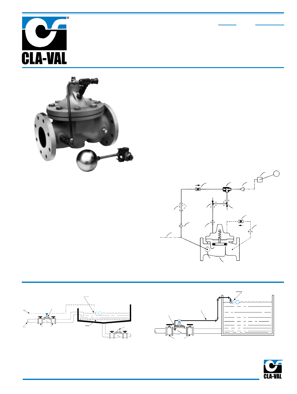
Typical Applications
Piping and Tank Sizing
Install valve and control as shown in the diagram above. The
float control should be located in a still liquid surface. If it is
necessary to obtain this condition, a stilling well should be
constructed. Mount the control on the connecting piping with
the outlet port at the desired high water level.
Filter Liquid Level Control
Maintains constant level in rapid sand filter.
Usually requires the use of an independent
operating pressure as shown.
Schematic Diagram
Item Description
1
Hytrol (Main Valve)
2
X47A Ejector
3
Bell Reducer
4
CFM2 Float Control
Optional Features
Item Description
A
X46A Flow Cleaner Strainer
B
CK2 (Isolation Valve)
C
CV Flow Control (Closing)
D
Check Valves With Isolation Valve
F
Independent Operating Pressure
S
CV Flow Control (Opening)
Y
X43 "Y" Strainer
• Accurate and Repeatable Level Control
• Proportional Flow
• Reliable Hydraulic Operation
• Drip Tight Positive Shut-off
• Completely Automatic Operation
The Cla-Val Model 129-01/629-01 Float Valve maintains a relatively
constant level in storage tanks and reservoirs by admitting flow into
the tank in direct proportion to the flow out of the tank. It is a
hydraulically operated, pilot controlled, diaphragm valve. The rotary
disc type float operated pilot control is installed at the high liquid level
in the reservoir and is connected via tubing or pipe to the main valve.
As the liquid level changes, the float control proportionally opens or
closes the main valve, keeping the liquid level nearly constant. If the
check feature option is added and a pressure reversal occurs, the
downstream pressure is admitted into the main valve cover chamber
and the valve closes to prevent return flow.
✣
The "D" feature on a vertically installed 6" and
larger valve must be horizontally installed.
129-01
629-01
TM
TM